
Flash light

The collective term flash are in the photography lighting equipment together, with a flash of light for the necessary object illumination at the moment of receiving care. In this context, one also speaks of flash photography .
Basics
Short, lightning-like lighting is sufficient in photography because of the relatively short exposure times . To do this, the time in which the flash is triggered and reflected by the object must be synchronized with the shutter speed of the camera. Since the flash glows very briefly compared to normal shutter speeds, it must be released at a time when the shutter is fully open. The shortest shutter speed at which a focal plane shutter completely releases the film or sensor at a time is called the flash sync speed .
Different effects and moods can be achieved in the photo using different flash methods .
An important criterion for flash light is the light color - specified in Kelvin . Most current flash units emit a neutral white light - similar to direct sunlight - from 5500 K to 6500 K. They can therefore be combined with sunlight without any problems (for example with fill-in flash). In interiors, for example, flash light looks rather cold compared to incandescent light , so mixed light should be avoided here - except for creative effect photography.
The guide number (LZ) of a flash is used to easily calculate the camera settings when using flash bulbs or manual settings for computer flash units.
The light angle of a flash unit stands for the maximum focal length of the lens at which the image recorded by the camera can still be fully illuminated.
In addition to the flashes integrated in the cameras or the attachable system flashes, so-called flash systems are used in the studio or on location .
history

In 1861 Eduard Liesegang, one of the founders of Ed. Liesegang oHG came up with the idea of igniting magnesium in order to use it as a light source in photography. There was a bright light. The amount of light was influenced by the duration and intensity of an air flow and was difficult to control. This was a particular problem with portrait photography.
1887 invented Adolf Miethe together with John Gaedicke the flash powder of magnesium, potassium chlorate and antimony sulphide . This powder only burned fractions of a second and thus resembled today's flash. The disadvantage was its high level of instability , which sometimes led to accidents.
The invention of the flashlight bulb by the physicist Johannes Ostermeier provided a remedy . In 1928 he discovered that pure magnesium or aluminum housed in a flash bulb in an oxygen atmosphere could be ignited electrically. This material burned like lightning in about 1/30 of a second with great brightness development. The disadvantage was that once used flash bulbs could not be reused.
Harold E. Edgerton , professor at the Massachusetts Institute of Technology (MIT), developed the first electronic flash device in the late 1930s that uses a flash tube to generate a short, very bright flash of light. This made it possible for the first time to take flash photos in quick succession.
The first camera with built-in flash synchronization was the Exakta Model B from the Ihagee company in Dresden in 1935 ; it worked with Osram Vacublitz flash bulbs.
Flash systems
Flashlight with an open flame
Magnesium light


Magnesium was recognized as a separate chemical element in 1755 by the British chemist Joseph Black (1728–1799). After Prof. Robert Bunsen (1811–1899) and Sir Henry Enfield Roscoe (1833–1915) had examined the properties of magnesium in more detail, Paul Eduard Liesegang (1838–1896) proposed in 1861 to take photos with magnesium light:
According to the photochemical studies by Bunsen and Roscoe, magnesium is an excellent source of actinic light. It catches fire with ease and burns with an extremely brilliant flame. ... According to Bunsen's research, the photogenic power of the sun is only 36 times stronger than that of burning magnesium. ... We do not believe that it has already been used for photographic purposes. "
The first flash light arrangements were blow lamps . Since pure magnesium only ignites at high temperatures, the pure magnesium powder in these lamps was ignited by blowing into a hot flame. A bright light was generated. The blowing was often created with a small rubber balloon by squeezing it with the hand, so that a kind of flash of light was created. The number of puffs of air and the duration of the blowing regulated the amount of light emitted. There was no short flash in the current sense. Thin magnesium foil, thin magnesium wire or thin, narrow magnesium tape also burned down in the air after lighting with a bright light and were used to generate light for photographic purposes until the Second World War.
In portrait photography , the bright magnesium light that suddenly flared up and lasted for a few seconds was a major problem as the models were dazzled and frightened. “Even if there is no excessive blurring, the result will be a tortured, dissimilar, frightened face, with a mindless expression and cancer-like bulging eyes”, as Adolf Miethe and Johannes Gädicke put it in their book Practical Guide to Photographing with Magnesium Light from 1887 to have.
Flash powder


John Traill Taylor found out in 1865 that magnesium powder mixed with potassium permanganate could be manually set on fire and then burned with very strong brief lights. In 1882, Seneca Ray Stoddard invented a camera-mounted flash lamp for flash powder for use in brightened night shots outdoors. The operation of these was still very dangerous. Stoddard was also occasionally burned. Adolf Miethe and Johannes Gädicke developed a lightning powder in 1887 by adding potassium chlorate and antimony (III) sulfide to the magnesium . George R. Lawrence improved the flashlight powder sold in the USA so that it burned brighter with less smoke, and made it electrically ignitable and invented an umbrella-like smoke catcher so that the ban on flashing was lifted indoors.
They were particularly concerned with how quickly it lights up with the same effective total amount of light. The lightning-like combustion in about 1/30 of a second made it possible to take pictures of people and living objects without the reaction to the bright flash being recognizable in the photograph. The flash powder mixture for which they had registered for a patent soon came into general use.
However, the mixture was highly explosive. There are reports of several major accidents with deaths and injuries in the explosion of entire flashlight powder factories. On May 30, 1903, the "Aktien-Gesellschaft für Anilin-Fabrikation in Berlin" ( Agfa ) patented flash powder mixtures containing nitrates of the elements thorium , cerium or zirconium . In addition to an increased light intensity, this resulted in a lower risk of explosion and smoke development reduced to 1/10 of the usual. However, the open fire, smoke, and the all-polluting magnesia layer remained the biggest problems with powder flash photography. In some silent films, too, accidents with flash powder were shown.
However, pouch flashes remained on the market until the 1960s because they were significantly cheaper than flashbulbs. They were paper bags filled with flash powder in the form of today's tea bags, to which a long prepared paper strip was attached as a fuse at the bottom. At the top was a hanging cord that could be used to attach the lightning bag to a broomstick, for example. One had to make sure that falling, still glowing remains of the lightning bag could not cause scorch damage.
The production of flash powder is subject to explosives law in Germany and is therefore prohibited for private individuals without the required examination.
Photographing with magnesium and flashlight powder was usually done without synchronization . In other words, the photographer first opened the camera shutter, then lit the flash as quickly as possible and then closed the shutter again.
Flash units for flash bulbs
The lightning bulbs brought an enormous improvement and made work easier compared to the flash powder. The bulb was ignited via an electrical synchronous contact, the M synchronization of the camera. The flash was triggered even before the shutter was fully open, as the chemical process of combustion had to start. This ensured that the shutter of the camera was fully open when the maximum brightness of the glass bulb flash was reached. As a rule, a capacitor was charged from a power source (battery or similar) via a series resistor before the lightning strike. The charged capacitor was then short-circuited via the lightning bulb and discharged in a defined manner, which ignited it.
- Flash units for flash bulbs

Leica IIIf (1951) with Leitz CTOOM flash rail and CEYOO flashing light
Agfalux 6872 - large compartment

Agfalux 6874 - smaller fan - fan out of the flash unit

Agfalux Ci - mini flash unit for flash cubes


Electronic flash units

As electronic flash , electronic flash or strobe unit is called a flash in the flash photography, with one on the 1938 by Harold E. Edgerton at the Massachusetts Institute of Technology developed the gas discharge tube based flash lamp is working. With the help of the filling gas Xenon, which is briefly under high pressure during the gas discharge, it emits light with a high color rendering index and a color temperature that roughly corresponds to that of daylight .
In Germany, the first such device was produced in 1948 by the company Dr. Ing. Mannesmann brought on the market.
The electronic flash unit emits light of high intensity for a short period (about 1/300 second down to about 1 / 40,000 second). With special constructions, recordings with an exposure time down to a millionth of a second are possible. These values are the duration of the light flash and have nothing to do with the flash sync time; the shortest exposure time in which the shutter of a camera is fully open and the flash fully delivers the desired output.
Mobile electronic flash units are either coupled to the camera via the hot shoe, connected to the camera with a synchro cable or triggered completely wirelessly as a so-called unleashed flash . Special radio triggers are usually used for wireless triggering, but there are also purely optical solutions that are triggered with a control flash.
Also known are more or less fixed studio flash units , which are also based on Edgerton's gas discharge tube.
The maximum amount of light from an electronic flash unit is usually given today with the guide number for a given film speed and a given angle of illumination. Other specifications are watt seconds ( joules ), which however indicate the electrical energy content of the storage capacitor. BCPS ( Beam Candle Power Seconds ) or ECPS ( Effective Candle Power Seconds ) indicate the product of illuminance and flash duration, i.e. direct information on the amount of light that can be achieved back into the camera.
The exposure can partly be varied via the flash duration: Some electronic flash units can interrupt the flash by short circuiting or interrupting the gas discharge based on the amount of light reflected during the course of the flash (see computer flash ). In modern camera systems, the control of the flash (light quantity counting) by the camera has become established, for example with TTL flash measurement .
The most common designs are the clip-on, stick and ring flash units . The latter is primarily used for uniform illumination in macro photography and to create certain light effects in portrait photography.
The following types of electronic flash units are common:
- Built-in flash unit - especially with compact cameras
- Clip-on flash unit (compact flash unit)
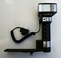
- Handheld flash unit (handheld flash unit)
- Studio flash unit
There are also adapter systems in order to be able to operate clip-on flash units with accessories as with the studio flash units.

Plug-on electronic flash

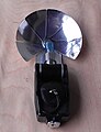
Front of an external flash unit

Modern clip-on flash unit

Classic handheld flash unit, here with a second reflector for brightening
Metz flash unit with SCA adapter for analog Canon cameras


Today's electronic flash units work with xenon-filled flash tubes that can be used ten thousand times. When triggered, a capacitor previously charged to a few hundred volts is discharged, which creates a very short, bright gas discharge inside the flash lamp . The typical burn time of this flash is between about 1/300 and 1 / 40,000 of a second, depending on the power and control. This is considerably shorter than with the " flash cubes" and must be taken into account when choosing the exposure time (see flash sync time , flash exposure metering and extension factor ).
Many modern photo cameras have a built-in flash. High-quality cameras also have a hot shoe on which external flash units can be attached. Since microelectronics found its way into camera technology in the mid-1980s, these have mostly been tailored to the respective camera model in order to interact with its automatic functions. Third- party manufacturers offer flash units that can be adapted to different cameras with flash adapters (SCA system).
The electronic flash has almost completely replaced earlier flash bulbs based on chemical combustion.
Computer flash
The first computer flash units were introduced almost simultaneously in the 1960s by Honeywell (USA) and Rollei . Since the computer emerged in the public consciousness at this time , this regulated flash unit was linked to the trend name of the time for image reasons. The part of the name “computer” was misleading, because no calculations in the sense of a computer program were carried out in the devices.
The technical function is a pure control: A sensor in the flash unit measures the reflected light from the image space and switches the flash off when a set threshold is reached. The exposure is correct.
Switching off prematurely can result in very short flash times that can even be used in ultra-short-term photography. While the standard flash duration of an uncontrolled electronic flash unit is approx. 0.001 s, the time can be reduced to 0.00002 s (20 µs) by quickly switching off the flash. This enables spectacular shots. For example, when the computer flash unit was introduced, Rollei advertised a picture showing a pistol bullet plowing its way through a (Skat) playing card along the plane of the paper.
The restriction to the pure control no longer applies to modern computer flash units, whose complex functions and control by the camera can only be implemented through the use of microprocessors.
Technical details

To understand how an electronic flash unit works, see Figure 1. The power supply draws its energy either from batteries, rechargeable batteries, or the normal power supply via appropriate adapters. It charges the lightning capacitor C to a voltage between 350 V and 500 V. With fresh batteries or fully charged accumulators, this should be done in 5 s to 7 s, this time is called the flash cycle time. If the batteries or accumulators are partially empty, you have to wait up to 60 s. A sufficient voltage at the capacitor C is usually indicated on the flash unit. The power supply must therefore step up the low battery voltage (3 V to 6 V) considerably, which is achieved using flyback converters or other constructions. The batteries (or accumulators) must be able to supply a considerable current (> 1 A) for the battery size. Most amateur devices allow 20 to 40 shots for a set of batteries, professional devices with larger lead batteries allow far more flashes.

If the capacitor is charged, the device is ready for recording. After the exposure is released, the opening shutter closes a contact in the camera, which activates the ignition device in the flash unit via the synchronous contact (external or integrated in the hot shoe). This sends a high-voltage pulse to the ignition electrode, which is usually located outside the flash tube, i.e. has no electrical contact with the inside.
This impulse causes an ionization of the gas (neon, xenon) in the flash tube. This makes the electrical resistance in the flash tube so small that the voltage on the capacitor is sufficient to generate a plasma in the flash tube . This plasma path has a very low electrical resistance. The capacitor is therefore discharged to a low residual voltage within 1/1000 s and the plasma goes out. The recording is finished and the camera shutter can close.
First generation computer flash units

In Figure 2 you can see how the control of the amount of light emitted was technically carried out in the regulated flash units of the first generation: A switching device was set parallel to the flash capacitor, which registered the light reflected from the object via a sensor. If the amount of light reflected was identical to the preset value, the switching device was activated, which immediately short-circuited the capacitor (t k in Figure 4). The voltage on the capacitor therefore collapsed immediately, which led to the plasma in the flash tube being extinguished.
Technically, the regulation was solved in such a way that the reflected light was picked up via a photodiode or a phototransistor . The more light these elements receive, the more electricity they let flow. This current is integrated in a capacitor. The voltage applied to the capacitor is therefore a measure of the exposure of the object to date by the flash. If the voltage has reached a set threshold, a thyristor is triggered, which is parallel to the lightning capacitor. This thyristor must be able to withstand high pulse currents, because the short circuit of the lightning capacitor generates peak pulse currents of up to several hundred amperes. There were also constructions in which the “external” flash tube was connected in parallel with a second “internal” flash tube, also called “quench tube” (“quench” comes from English and technically means “push something away”). This was ignited in the same way as the external tube and resulted in extinction of the external tube. This type of circuit managed without a thyristor.
The disadvantage of these designs was that every time the flash was triggered, the full energy of the flash capacitor was lost. The flash capacity of such a flash unit was therefore the same as that of an electronic flash unit without control.
Second generation computer flash units

Just a few years after the introduction of the first “computer flash device”, the second generation devices came onto the market. As can be seen in Figure 3, the short-circuit device has been replaced by a real disconnection device for the lightning current. This means that the energy stored in the capacitor is no longer lost when it is switched off. The power supply usually only has to deliver a little energy. Under favorable circumstances, the flash recycle times were reduced to less than 1 s, and rapid flash sequences with winder or motorized camera operation are also possible. With the same or even smaller batteries, a significantly higher number of flashes per battery set (or per battery charge) was achieved than before. The devices could indicate adequate flash exposure.
This was technically possible because thyristors with very short switch-off times were now available. Thyristors are direct current switching elements which, when ignited, only switch off again when the cathode (negative pole) receives the same or even positive potential compared to the anode (positive pole). When the flash is triggered, not only is the ignition device activated, but a thyristor is also ignited, which conducts the lightning current from the flash tube to minus. The reflected light is still measured. When the trigger threshold is reached, a second thyristor is triggered, which uses an electronic trick to apply a short positive voltage pulse to the cathode of the main thyristor. This causes it to lose its conductivity and the lightning current is switched off. Another device checks whether at this moment there is still a voltage on the flash capacitor that is higher than the residual voltage that remains after the plasma has been extinguished in operation without automatic. If this is detected, a lamp lights up to indicate that the exposure from the flash was sufficient.
The devices still work on this basis today.
TTL control
The first flash units emitted the light at an angle that was set so that a picture with the normal lens was illuminated with an angle of view of approx. 45 °. If a telephoto lens is used when taking the picture or a wide-angle lens whose image field illumination may have been indirectly flashed (e.g. against the ceiling), the sensor built into the flash unit, which is also set to 45 °, can use the Incorrectly capture the situation and incorrect exposures can result.
So it made sense to measure the flash exposure in the camera. This is always done so that the sensor in the camera sits behind the lens and is aligned with the film. It measures the light reflected from the film plane. The measurements are passed on to the electronics in the flash unit via additional contacts in the hot shoe. This measurement method is TTL (Engl. T hrough T he L ens) called (as well as the normal light metering at SLR).
Unfortunately, the manufacturers could not agree on a common mechanical, electrical and functional connection. The SCA-300 and later the SCA-3000 system was therefore developed in Germany, with which third-party flash units (e.g. from Metz, Cullmann and others) can be connected to the proprietary connections of the large camera companies.
The relocation of the flow of information from the sensor to the flash unit in the contacts of the hot shoe previously prevented the flash unit from becoming detached from the camera, which is sometimes necessary to achieve a better picture effect. Here the TTL system had its limits or required unwieldy accessories such as extension cables. Today, TTL-capable flash units can easily be triggered remotely over distances of up to 100 m with TTL data-transmitting radio remote triggers.
Refinements of the TTL system are pre-flashes of the flash unit, which are evaluated by the camera via TTL sensors with several sectors before the actual main flash is emitted to determine the subject contrast (first introduced in 1992 for the Nikon F90 reflex camera ). This enables even more precise control of the flash exposure, especially for very high-contrast or low-contrast subjects.
Studio flash systems can also be controlled via TTL regulation, whereby the manual control or control with flash exposure meters and Polaroid instant images is mostly preferred by experienced professional photographers.
Exposure control


The exposure is controlled for flash photos by the set aperture and the light output of the flash unit. With studio flash units and better flash units, the reflector can also be swiveled and, if necessary, rotated so that the light reflected from a white surface (e.g. ceiling) does not flash directly, but rather indirectly. Except in special cases, the shutter speed has no influence on the actual flash exposure. An automatic exposure system built into the camera, which can control both the flash and the lens iris, is particularly convenient. However, electronic flash units with independent light control also generally allow reliably correct flash photos. Without such automatics, you need a flash exposure meter , or you work according to tables and empirical values. The histograms of modern digital cameras are also a good aid . In order to achieve the shortest possible flash sync times, the shutter curtains must run as quickly as possible. For this purpose, various efficient techniques have been developed over time.
So-called system flash units work closely with the camera and relieve the photographer of such settings in automatic mode. You adapt the flash output and / or the aperture to the current light situation. In this case - in not too dark environment - often still a long exposure time elected to the available light ( Available Light ) to capture and disturbed by the flash light mood as little as possible.
With many flash units, the guide number can also be reduced in stages (usually to 1/2, 1/4, 1/8, etc.).
In the case of multiple exposure, the intermittent effect must be taken into account.
Use in digital cameras
The reflection properties of the image converters in digital cameras can only be compared to a limited extent with those of a 35mm film. TTL control by evaluating the reflections from the image converter may therefore lead to unsatisfactory results and is therefore not available with most digital camera models.
The flash exposure is therefore often determined using a pre-flash. Sometimes the distance set on the lens (auto focus or manual setting) is also included in the calculation of the flash duration. These pre-flash measurements are z. This is used, for example, in digital SLR cameras from Canon (E-TTL; E-TTL 2), Nikon (D-TTL, I-TTL), Pentax (P-TTL) and Konica Minolta / Sony (ADI).
Artificial exposure extension
.jpg)
A problem with flash exists with cameras with a focal plane shutter . This construction is usually used with single-lens reflex cameras. Looking downwards from long shutter speeds, for example 1 second, the second shutter curtain only remains completely behind until the so-called synchronous time when the first curtain has already reached the end point. Only then is the entire image area exposed for a moment, and the flashed image that is released by the first curtain when it reaches the end position is still complete.
With modern 35mm cameras, this synchronization time is in the range from 1/45 to 1/250 second (with central shutters and electronic shutters up to 1/500 second, sometimes even shorter). With faster shutter speeds, the second curtain will already start rolling if the first is still on the way. This is the exposure slot that gives this type of shutter its name. If the flash is now triggered by the first curtain, part of the negative is covered and only a narrow strip of the negative is exposed to flash.
The company Olympus had built a computer flash for the OM camera system for the first time, which fires a whole series of extremely short single flashes ( stroboscope ) for this situation and therefore allows flashes in the area to be shorter than the usual synchronous time even with a focal plane shutter. This so-called high-speed synchronization has been adopted by all major manufacturers of cameras in the small picture area. The prerequisite is the use of a suitable system flash unit. The Minolta Dynax 9 single-lens reflex camera , in conjunction with a suitable flash unit, uses a similar technology to achieve flash synchronization times of 1 / 12,000 seconds.
Image fulgurator
The Image Fulgurator (Latin for flash thrower) describes an invention patented in 2007 by Julius von Bismarck.
See also
literature
- Horst Schrader: Today's flash. 2. rework. extended edition hall: photo cinema
- Ulrich Mohr: The Multiblitz Photography. Advice and suggestions for taking pictures with electronic flash devices. Drei Mohren Verlag, Hamburg 1954
- Günter Olberg: The electronic flash and its use with special consideration of portrait photography. Practitioner's experience . Knapp, Halle 1954
- Pierre Bron, Philip L. Condax: The Photo Flash. His story . Bron Elektronik AG, Allschwil 1998, ISBN 3-9521472-1-4
- A. Miethe, J. Gädicke: Practical instructions for photographing with magnesium light. Published by Robert Oppenheim, Berlin 1887
- Heinrich Freytag and Otto Sahmel: The flash book. Flash powder, capsule flash, flash lamp, strobe . Knapp, Düsseldorf 1954
- Jürgen Philipp: Blitzpraxis analog and digital. Lighting basics . 160 pages. vfv Verlag, Gilching 2002, ISBN 3-88955-132-7
Web links
Individual evidence
- ^ Seneca Ray Stoddard in the New York State Archives
- ↑ Archive link ( Memento of the original from September 5, 2008 in the Internet Archive ) Info: The archive link was inserted automatically and has not yet been checked. Please check the original and archive link according to the instructions and then remove this notice. about Flashlight Lawrence by Janice Petterchak.
- ↑ Mulitblitz Manufaktur for premium studio flash systems ( Memento from January 19, 2017 in the Internet Archive ), multiblitz.de, accessed on October 19, 2016
- ↑ Blog post about Flash2Softbox with sample photos (English) Archive link ( Memento from January 5, 2012 in the Internet Archive )
- ↑ Control flash units outside the camera ( Memento from December 22, 2011 in the Internet Archive )