Crossover (loudspeaker)
A crossover divides an audio signal over several loudspeakers depending on the pitch ( frequency ). High-quality loudspeakers such as tweeters and woofers are only optimized for a narrow frequency range due to their design. The combination of several different types of loudspeakers in loudspeaker boxes for different frequency ranges requires corresponding crossovers.

General
Since most loudspeakers can only cover the frequency range from approx. 20 Hz to approx. 16 kHz that can be heard by humans by using different drivers for low, mid and high frequencies, the signals to be reproduced are transmitted before or after the audio amplifier with the aid of a crossover network split into different frequency ranges. These sub-frequency bands are then output via the loudspeaker chassis, such as tweeters and woofers, which have been optimized for the respective frequency bands. In contrast, broadband loudspeakers manage without a crossover, but often also require active equalization or special loudspeaker housings such as horns . This can be useful because a crossover always influences the sound and a point sound source is aimed for for optimal spatial imaging. This can also be implemented with coaxial speakers , which in turn require a crossover.
The structure of the crossover is essentially a combination of high- pass and low-pass filters and in the simplest case consists of capacitors and coils . Capacitors allow higher frequencies to pass and block low frequency components, with coils it is exactly the opposite. By appropriately combining these properties, if necessary in combination with resistors for damping, the necessary filter functions can be created.
In addition to the filter function, the crossover also serves to linearize the frequency response ; the crossover is adapted to the properties of the loudspeaker for this purpose. In addition, the level of the loudspeakers can be adjusted in some extended crossovers, combined with protective functions such as overload protection by means of limiters or in the form of PTC thermistors , which increase their resistance when heated and thus limit the power output to the loudspeakers.
Embodiments
Crossovers can be implemented in the following basic variants:
- Analog passive crossover: Consists only of passive electronic components such as capacitors, coils and resistors. There is no amplification, the crossover does not require any additional supply. In practice, filters with filter orders from 1st to 4th are common.
- Analog active crossover: Active components such as transistors or operational amplifiers are also used. Crossovers of this type require a supply for the active components, the filter orders are usually between 2nd and 8th order.
- Digital switch: The filter function is implemented in the form of a digital filter in digital signal processors (DSP). The interface could be analog-to-digital and digital-to-analog converter for use, in addition to corresponding amplifier stages. These crossovers, which are usually much more complicated in structure - they can also be used to implement very high filter orders - also require a corresponding power supply for operation.
In practice, these three basic shapes can also be used to form various combinations. For example, the equalization function can be performed by active analog circuit components, but the actual crossover network is purely analog-passive in structure.
Analog passive crossover
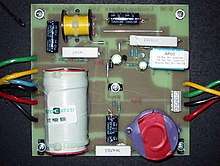
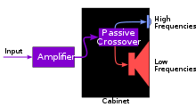
Passive crossovers are usually used after the last amplifier stage and immediately before the loudspeaker, and in many cases they are also integrated into the loudspeaker housing. By adapting the frequency response to the loudspeaker, with lossy and passive components, part of the electrical energy supplied is converted into heat. An equalization of the bass path is therefore usually not possible, as the output amplifier would be overloaded. Due to the performance, the necessary components are dimensioned correspondingly large, this is especially true for the coils.
The main advantage of passive crossovers is that a single power amplifier is sufficient to drive a loudspeaker and the crossover does not require an additional power supply.
The illustration opposite shows a simpler filter circuit of a two-way switch with high and low pass filters of the 2nd order. From filters of the 2nd order upwards, the filter quality can be influenced by the selection of the component values relative to one another. This fact manifests itself in a different electrical amplitude and phase response in the area of the filter corner frequency.
Instead of the bandpass filters, which are more complex to implement, with only two output stages , low-pass filters that are easier to implement for the woofer and a high-pass filter for the tweeter are also used.
Analog active crossover
Active crossovers have electronic amplifiers with components such as operational amplifiers and transistors in the filter stages . The amplifiers from the output stage to the loudspeakers are then connected downstream of the crossover network. This means that the crossover network and the filter stage can be implemented with smaller components. The disadvantage of passive crossover switching, such as insufficient equalization of the low-frequency path, can thus be avoided. In this way, overload monitoring can also be implemented more easily in the individual output stages.
The disadvantage is that a separate amplifier is required for each output stage, including an additional power supply.
Digital switch
In digital switches, the actual filter functions are carried out in a digital signal processor in the form of digital filters for frequency division, for equalization and for time-of-flight correction of the signals. For this purpose, the input signal supplied, if it is not already digital, is digitized using an analog-to-digital converter (ADC). Digital turnouts are always active turnouts and need their own power supply.
A separate output with digital-to-analog converter (DAC) and - as with the analog active crossover - a downstream amplifier stage is required for each frequency range .
The increased effort in the form of additional A / D and D / A converters as well as additional output stages compared to the passive crossover are offset by the advantage of the expanded possibilities that result from digital signal processing . This includes more complex, stable and reproducible filter functions as well as the possibility of being able to freely adapt these functions at any time - even during operation - without physical intervention.
In addition, interfaces for remote controls or status displays can be available for digital switches . In professional audio technology, these switches are also called “system controller DSPs” or “loudspeaker management systems”. They are usually connected between the mixer and the power amplifier (output stage).
literature
- Götz Schwamkrug: Loudspeaker boxes: assembly - replica - conversion . 2nd Edition. Elektor-Verlag, Aachen 1989, ISBN 3-921608-83-X .
- Wolfgang-Josef Tenbusch: Basics of the loudspeakers . 1st edition. Michael E. Brieden Verlag, Oberhausen 1989, ISBN 3-9801851-0-9 .
- Berndt Stark: Loudspeaker manual . 8th edition. Richard Pflaum Verlag GmbH & Co.KG, Munich 2004, ISBN 3-7905-0904-3 .


