
Polymer electrolytic capacitor


A polymer electrolytic capacitor , abbreviation “ polymer electrolytic capacitor ”, is a polarized capacitor , the anode ( + ) of which consists of a metal ( valve metal ), on which an even, extremely thin electrical voltage adapted to the nominal voltage is deposited on it by anodic oxidation , also called formation insulating oxide layer is generated as a dielectric . A solid electrolyte made of a conductive polymer , which geometrically adapts to the surface structure of the anode, forms the cathode ( - ) of the capacitor. Based on the anode metal used and the combination of polymer electrolyte with a liquid electrolyte, there are three different types:
- Polymer tantalum electrolytic capacitors
- Polymer aluminum electrolytic capacitors and
- Hybrid polymer aluminum electrolytic capacitors
Polymer niobium electrolytic capacitors have not yet gone into series production.
Polymer capacitors are characterized by very low (values ESR) equivalent series resistance ( ESR equivalent series resistance and high) of ripple current ratings from. This means that they are in competition with ceramic multilayer chip capacitors (MLCC), but offer higher and voltage -independent capacitance values than MLCC capacitors, and they also have no microphonic effect.
Polymer electrolytic capacitors are offered as cylindrical or cuboid SMD designs or as wired versions in a radial (upright) design. Their electrical parameters are significantly less dependent on temperature and have a significantly longer service life than aluminum electrolytic capacitors with liquid electrolytes, but have higher residual current values than these.
Polymer electrolytic capacitors are also offered in a hybrid design. The hybrid polymer aluminum electrolytic capacitors have both a solid polymer electrolyte and a liquid electrolyte. In addition to the low ESR values, this embodiment is also characterized by low residual currents and by insensitivity to transients , but has a shorter service life than pure polymer capacitors.
Due to the large specific capacitance, the low ESR and the available flat SMD designs, polymer electrolytic capacitors are particularly suitable for devices with a flat design, such as laptops , mobile phones , digital cameras and flat screens. Here they are used to decouple unwanted frequencies from the double-digit Hertz range up to a few megahertz, to smooth rectified voltages in switched-mode power supplies and to buffer the power supply of digital circuits in the event of a sudden power requirement.
Importance of digital technology for polymer electrolytic capacitors
Basic electrolytic capacitor applications
The main area of application of electrolytic capacitors is in the field of power supplies for electronic devices. Here, after the rectification , they smooth or suppress the rectified AC voltage and buffer or stabilize the DC voltage in the event of a sudden power requirement in the downstream circuit. With DC-DC converters , electrolytic capacitors can also fulfill a buffer function on the input side. There are a number of terms for these applications, such as smoothing capacitor , filter capacitor ( bypass capacitor ), backup capacitor ( bulk capacitor ) and decoupling capacitor ( backup capacitor ).
In these applications, in addition to the capacitance, the impedance Z, the series equivalent resistance ESR ( Equivalent Series Resistance ) and the series inductance ESL ( Equivalent Series Inductance ) are important electrical parameters for assessing the properties of these capacitors in the circuits.
Digitization - The ESR Challenge

Current high-performance processors have power consumption of 5 A (mobile devices) to 300 A (high-end server) with operating voltages of 0.6 to 1.35 V, which must be maintained at 0.01 to 0.02 V. These requirements are a major challenge for the power supply. Because the ESR of the capacitor results in a voltage drop in the event of a sudden power requirement
- ,

which affects the functionality of the downstream circuit.
The following values may serve as an example of the orders of magnitude that must be observed in modern circuits: The supply voltage of a processor is 1.1 V with a permissible tolerance of 0.02 V and the current consumption fluctuates between 10 and 90 A. This requires a Internal resistance of the power supply ESR = U / I = 0.02 V / 80 A = 0.25 mΩ. This is why there are countless backup capacitors already on the chip PCB, and more near the base. Processors also communicate directly with the voltage converters in order to be able to communicate their current and voltage requirements directly. There are also adjustable negative output resistances of the power supply (called load line calibration)
Only through the development of new, solid electrolytes, first TCNQ, then the conductive polymers, which led to the development of the polymer electrolytic capacitors with their very low ESR values combined with high capacitance values, as well as through design measures such as multi-anode technology, the Demands for ever smaller ESR values in the capacitors for power supplies of the increasingly complex digital circuits can be met, see #New constructions - reduction of ESR and ESL .
However, as the integration density increased, so did the switching speeds of the microprocessors. Faster switching edges, however, required lower parasitic inductances, and the ESL of the capacitors had to be reduced. Further design measures for tantalum polymer electrolytic capacitors such as the face-down technology or the layered structure of the aluminum polymer electrolytic capacitors were also able to meet these requirements.
Basics
Plate capacitor

All electrolytic capacitors are basically plate capacitors, the capacity of which is greater, the larger the electrode area and the relative permittivity and the smaller the distance between the electrodes.


In order to increase the capacity of the later capacitor, the anode of all electrolytic capacitors is roughened, making the surface significantly larger than that of a smooth surface, which does not change the principle of the plate capacitor.
The dielectric constant is made up of the electric field constant and the material- specific permittivity of the dielectric :


- .

This value then determines the specific capacitance of aluminum or tantalum polymer electrolytic capacitors.
Anodic oxidation (formation)


Polymer electrolytic capacitors are based on the electrochemical effect of anodic oxidation ( formation ). Here, on the surface of so-called. Valve metals ( aluminum , tantalum , niobium u. Am) by applying the positive pole of a direct current source placed in a part connected to the negative pole bath with a liquid electrolyte , an electrically insulating oxide layer formed as a dielectric of a capacitor to be used can.
These oxide layers on the anode (+) are very thin and have a very high dielectric strength , which is in the nm / V range. The capacity of this capacitor is determined as to a capacitor plate from the geometry of the anode surface and the thickness of the oxide layer. This is determined with the forming voltage and can thus be adapted to the requirements of the respective application, whereby an optimization of the specific capacity is possible.
materials
Anodes
The main difference between the polymer capacitors is the anode material used and its oxide as a dielectric:
- Polymer-tantalum electrolytic capacitors use high-purity, finely powdered and sintered tantalum powder as the anode with tantalum pentoxide Ta 2 O 5 as the dielectric and
- Polymer-aluminum electrolytic capacitors use a high-purity and electrochemically etched (roughened) aluminum foil as the anode with aluminum oxide Al 2 O 3 as the dielectric
The material properties of the dielectrics produced by the anodic oxidation determine the specific capacitance of the respective capacitor type. The oxide structure also plays an important role. The following table gives an overview of the properties of the different oxide materials.
| Anode material | dielectric | Oxide structure |
Relative permittivity |
Durchschlags- strength (V / micron) |
Oxide layer thickness (nm / V) |
|---|---|---|---|---|---|
| aluminum | Aluminum oxide Al 2 O 3 | amorphous | 9.6 | 710 | 1.4 |
| crystalline | 11.6 ... 14.2 | 800 ... 1000 | 1.25 ... 1.0 | ||
| Tantalum | Tantalum pentoxide Ta 2 O 5 | amorphous | 27 | 625 | 1.6 |
If the values of the two anode materials are compared with one another, tantalum pentoxide has a permittivity that is approx. 3 times higher than that of aluminum oxide. Tantalum electrolytic capacitors could therefore theoretically be smaller than aluminum electrolytic capacitors with the same capacitance and nominal voltage value. In real polymer electrolytic capacitors, however, the oxide layer thicknesses, especially in the case of tantalum capacitors, are sometimes formed considerably more than the later nominal voltage of the capacitor would actually require. This is done for safety reasons in order to obtain a lower failure rate. For this reason, possible dimensional differences, which are derived from the different permittivities, are in some cases not effective.
Anode structures
One reason for the relatively high specific capacity of the electrolytic capacitors compared to other conventional capacitors is the greatly enlarged surface of the anode. In the case of aluminum electrolytic capacitors, the anode foil is electrochemically etched; in the case of tantalum electrolytic capacitors, the anode surface is significantly larger than a smooth surface by sintering fine powders. For small tensions, it can be up to a factor of 200 larger than a smooth surface.
- Structures of the anode materials of electrolytic capacitors

The anode foils of Al-Elkos are electrochemically etched (roughened), left: 10 V low-voltage anode foil, right: 400 V high-voltage anode foil.
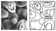
Sintered tantalum powder with an oxide layer on top.


Both the etching of the aluminum anode foil and the sintering of the tantalum or niobium powder create a roughened anode, the surface of which is significantly larger than that of a smooth surface.
Formation of the dielectric
To describe the chemical processes involved in the formation of
- Al electrolytic capacitors, see Aluminum electrolytic capacitor , from
- Ta electrolytic capacitors see Tantalum electrolytic capacitor .
Electrolytes
The electrolyte , which adapts to the surface structure of the oxide layer on the anode (+), basically forms the cathode (-) of the capacitor. The most important electrical property of an electrolyte in an electrolytic capacitor is its electrical conductivity . The electrolyte, the namesake of the electrolytic capacitor, forms the cathode of the capacitor. Since the roughened structures of the anode surface are continued in the structure of the oxide layer, the dielectric, this counter electrode, the cathode, has to adapt to the roughened structure as precisely as possible. This is easy to achieve with a liquid like in a conventional "wet" electrolytic capacitor. In the case of polymer electrolytic capacitors, in which a conductive polymer forms the electrolyte, which only receives its conductivity through a chemical process known as polymerization, this is much more difficult to achieve. However, the advantages of a solid polymer electrolyte, the significantly lower ESR of the capacitor and the low temperature dependence of the electrical parameters, in particular the impedance, often justify the additional effort in production and the higher costs.
TCNQ electrolyte

Electrolytic capacitors with the charge transfer salt tetracyanoquinodimethane TCNQ as electrolytes, which at that time were manufactured by Sanyo with the trade name “OS-CON”, were not “polymer electrolytic capacitors” in the true sense of the term “polymer”. TCNQ electrolytic capacitors are mentioned here to indicate the risk of confusion with "real" polymer electrolytic capacitors, which are now available under the same trade name OS-CON.
The original OS-CON TCNQ capacitors from the then manufacturer Sanyo were discontinued with the integration of the Sanyo capacitors by Panasonic. The OS-CON electrolytic capacitors now manufactured by Panasonic have a conductive polymer electrolyte.
Polymer electrolyte
A polymer is created through a chemical stringing together of individual molecules, known as polymerization . This is a chemical reaction in which monomers are continually added to a growing polymer . Usually, from an electrical point of view, polymers are insulators , at best semiconductors . However, conductive polymers are required for use as cathode material in electrolytic capacitors . The conductivity of a polymer is achieved through conjugated double bonds , which allow charge carriers to move freely in the doped state . Therefore, electrically conductive polymers have an extensive pi-electron system in the form of conjugated double bonds . Defect electrons serve as charge carriers . This means that the conductivity of conductive polymers, which is comparable to that of metallic conductors, only sets in when the polymers are oxidatively or reductively doped.
The requirements for a polymer electrolyte are diverse. It has to penetrate deep into the pores in the roughened anode in the finest branches in order to form the most complete, homogeneous layer possible, because only parts of the anode covered by the electrolyte contribute to the total capacity. For this purpose, the particle size of the basic polymer substances must be small enough before the polymerization to be able to penetrate into the small structures of the roughened anodes. The size of these polymer particles limits the degree of etching of the aluminum anode foils or the fineness of the tantalum powder. The rate of polymerization must be adapted to the mass production of capacitor production, i.e. H. Too fast a polymerization would not lead to a complete coverage of the anode, too slow a polymerization would increase the production costs. Neither its chemical precursors nor its chemical properties in the polymerized state nor its possible residues may chemically or mechanically attack the oxide on the anode. As a finished electrolyte, it should have great stability over a wide temperature range and maintain this over a long period of time. The polymer film is then not only the counter electrode of the capacitor, it also protects the dielectric against external influences such as e.g. B. the direct contact of graphite in the embodiments that are provided with a cathode contact via graphite and silver.
The polymer electrolytic capacitors manufactured today (2015) use two different conductive polymers. These include polypyrrole , PPy for short, the first conductive polymer that was used as a cathode material in electrolytic capacitors, and poly-3,4-ethylenedioxythiophene , PEDOT for short .
Polypyrrole PPy


Polypyrrole is made by the oxidative polymerization of pyrrole . A suitable oxidizing agent is iron (III) chloride (FeCl 3 ). Water, methanol, ethanol, acetonitrile and other polar solvents can be used for the synthesis. As a solid polymer electrolyte, it achieves conductivity values of up to 100 S / m.
Polypyrrole was the first conductive polymer used in polymer electrolytic capacitors, which was initially used in polymer-aluminum electrolytic capacitors and a few years later also in polymer Ta electrolytic capacitors. The in situ polymerization of the PPY polymer in the narrow pores of the anode structure is difficult to implement. When pyrrole is mixed with the desired oxidizing agents at room temperature, the polymerization reaction begins immediately. This means that polypyrrole begins to form before it has penetrated the pores of the anode. The rate of polymerization can be influenced by two methods, by cooling the basic substances to very low temperatures or by electrochemical polymerization. Both in situ methods are complex and require the polymerization to be repeated many times.
The method of cooling the basic substances to very low temperatures requires a great deal of technical effort and is unfavorable for mass production. In the case of electrochemical polymerization, an auxiliary electrode layer must first be applied to the dielectric and connected to the anode. For this purpose, ionic dopants are added to the basic substances of the polymer, which form a conductive layer on the surface of the dielectric during the first impregnation. During the subsequent impregnation, the in situ polymerization can be controlled over time by applying a voltage between anode and cathode with the current then flowing. A fine and stable polypyrrole layer forms on the dielectric of the later capacitor.
Both methods of in situ polymerization, however, require multiple cycles of impregnation and subsequent cleaning processes, which makes the production of polymer electrolytic capacitors costly.
The polypyrrole electrolyte has two fundamental disadvantages. It is toxic during the manufacture of the capacitors and becomes unstable at the higher soldering temperatures when soldering with lead-free solders.
Polythiophene PEDOT and PEDOT: PSS


Poly-3,4-ethylenedioxythiophene , abbreviated to PEDOT or PEDT, is a monomer based on 3,4-ethylenedioxythiophene or EDOT. PEDOT can be chemically polymerized by an oxidizing agent, e.g. B. by iron (III) sulfate . The reoxidation of iron is given by sodium persulfate . PEDOT is transparent, non-toxic, temperature stable up to 280 ° C and, as a solid polymer electrolyte, achieves conductivity values of up to 500 S / m. Especially due to its temperature resistance, it can be used to manufacture polymer electrolytic capacitors that withstand the increased soldering temperatures of lead-free soldering and also have even better ESR values than PPY electrolytic capacitors.
The difficult methods of in situ polymerization of PEDOT in the anodes of the capacitors were initially the same as with polypyrrole. This changed with the development of pre-polymerized dispersions in which the anodes of the capacitors are simply immersed at room temperature and then dried. To the PEDOT is sodium - polystyrene sulfonate (PSS) and dissolved in water. The complete polymer layer on the dielectric is then composed of pre-polymerized particles from the dispersion. These dispersions are known under the name PEDOT: PSS, trade names: Baytron and Clevius ™.
These PEDOT: PSS dispersions are available in different versions. For capacitors with high capacitance values with highly roughened aluminum anode foils or fine-grained tantalum powders, dispersions with very small particle sizes are available. The average size of these particles is around 30 nm, so that even the finest capillaries in the anode structures can still be soaked. Another variant of the PEDOT: PSS with larger particles, which polymerize to form a relatively thick layer, was developed as an enveloping protection of the capacitive cell of rectangular Ta and Al polymer capacitors.
Polymer electrolytic capacitors produced with PEDOT: PSS dispersions are also suitable for producing polymer capacitors with higher nominal voltage values of 200 V and 250 V. In addition, the residual current values of the polymer electrolytic capacitors produced with these dispersions are significantly lower than those of polymer electrolytic capacitors with in situ polymerized polymer layers. In addition to better ESR values, higher temperature stability and lower residual current values, however, the easier production of polymer capacitors from the pre-polymerized PEDOT: PSS dispersion, in which the dielectric can be almost completely covered with a polymer layer with just three dipping processes and the production is significantly less expensive, the main advantage of this polymer electrolyte.
Hybrid electrolyte
The hybrid polymer aluminum electrolytic capacitors are relatively new. They combine a coating of the roughened and oxidized anode structure with the conductive polymer with a liquid electrolyte. This fills the paper separator (spacer) and uses its ion conductivity to establish contact between the polymer electrolyte on the dielectric and a polymer layer on the cathode foil. The liquid electrolyte can supply the oxygen for self-healing or reforming of the capacitor, whereby the safety margin for the oxide layer thickness required for a certain dielectric strength can be reduced. In addition, the residual current is reduced by the self-healing so that values like conventional “wet” electrolytic capacitors can be achieved. The effects of the liquid electrolyte on the ESR and the temperature behavior are relatively small. By using appropriate organic electrolytes and by good sealing, a long service life can be achieved without premature drying out.
Types and forms
Polymer capacitors are available in three different types, based on the anode metal used:
- Polymer tantalum electrolytic capacitors
- Polymer aluminum electrolytic capacitors
- Hybrid polymer-aluminum electrolytic capacitors
These three different types, also called families, are produced in two different designs,
- as a cuboid SMD design , usually with a molded plastic housing and
- in a cylindrical design with a wound cell installed in a metal housing.
- Types of polymer electrolytic capacitors
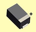
The cuboid SMD designs are available for polymer tantalum and aluminum electrolytic capacitors.
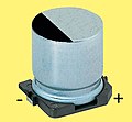
The cylindrical design (here the V-chip design) is only available for polymer-aluminum and hybrid-polymer electrolytic capacitors.


While the cylindrical polymer capacitors are clearly always aluminum electrolytic capacitors, it is not possible to assign the respective capacitor to an anode material in the case of the rectangular polymer capacitors.
A comparison of the capacitance and voltage values currently available with these designs is shown in the table under #Comparison of the basic values .
Polymer-tantalum electrolytic capacitors in cuboid design
Polymer tantalum electrolytic capacitors are basically tantalum electrolytic capacitors in which the electrolyte is not manganese dioxide but a conductive polymer, see also Tantalum electrolytic capacitor manufacturing process .
The basic material of the capacitor is a powder made of high-purity tantalum, which is mixed with a binding agent and then pressed together with a tantalum wire to form a round or cuboid block. This block is then sintered at high temperatures. The powder grains are fused together in a metallic manner. They are then connected in an electrically conductive manner and mechanically firmly joined together. A large number of pores remain in the sintered tantalum block, which run through the entire sintered block and form a very large surface area of the anode.
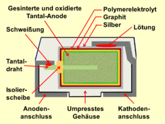
The surface of the sintered anode is oxidized according to the desired dielectric strength of the later capacitor. The oxide layer forms the dielectric of the capacitor. Then the sintered block is impregnated with the ingredients of the polymer, which is then polymerized into the conductive polymer in a chemical process. For contacting, the polymer layer is coated with graphite and silver, to which the cathode connection can be soldered. Depending on the requirement profile, the capacitive cell is then encased with a synthetic resin or built into a metal housing to ensure protection against moisture or other environmental influences.
- Construction principle of the cuboid shape for polymer tantalum electrolytic capacitors

Basic layer structure of a polymer Ta electrolytic capacitor with sintered anode and graphite / silver cathode contact
Basic cross-section through a cuboid polymer Ta chip capacitor

Cuboid-shaped polymer Ta chip capacitor


The development of polymer tantalum electrolytic capacitors in the early 1990s coincided with the development of devices with a flat design, such as cell phones and laptops, using SMD assembly technology. For this reason, the rectangular design of the polymer tantalum electrolytic capacitors was the best solution. Due to the rectangular base, the assembly space is used to the maximum, which is not the case with round bases. In addition, the sintered cell can be manufactured in such a way that the finished SMD component has a desired overall height. In many cases this is the height of the processors or other semiconductor components used. Typical for this is, for example, the overall height of around 2 to 4 mm.
Polymer-tantalum electrolytic capacitors have ESR values that are only about 1/10 of the value of tantalum electrolytic capacitors of the same size with manganese dioxide electrolytes. Thanks to multi-anode technology, in which several anode blocks connected in parallel are built into one housing, the ESR value can be halved again. In addition to the very low ESR values, the advantages of multi-anode technology are primarily the lower inductance, which makes the capacitors suitable for higher frequencies.
The only disadvantage of all polymer-tantalum electrolytic capacitors is the residual current, which is approximately 10 times higher than that of the versions with manganese dioxide electrolytes.
Polymer SMD tantalum electrolytic capacitors are available up to a size of 7.3 mm × 4.3 mm × 4.3 mm (length × width × height) with a capacity of 1000 µF / 2.5 V. They can cover temperature ranges from −55 ° C to +125 ° C and are available in nominal voltage values from 2.5 to 125 V.
Polymer-aluminum electrolytic capacitors in cuboid design
The rectangular polymer aluminum electrolytic capacitors are aluminum electrolytic capacitors with one or more layered aluminum anode foils and a conductive polymer as the electrolyte. The layered anode foils are contacted with one another on one side, this block is anodically oxidized, i.e. H. the dielectric is produced and the block is then provided with the polymer electrolyte using suitable methods. The cathode foils used in wound electrolytic capacitors with cylindrical designs for contacting the electrolyte are omitted; instead, the cathode contacting of the polymer electrolyte takes place via a layer of graphite and silver, as with the polymer-tantalum electrolytic capacitors.
- Construction principle of the cuboid design for polymer aluminum electrolytic capacitors

Cross-section through the capacitive cell of a polymer aluminum electrolytic capacitor with graphite / silver cathode contact.

Cross-section through a cuboid SMD polymer aluminum electrolytic capacitor encased in synthetic resin with graphite / silver cathode contact.

Cuboid SMD polymer electrolytic capacitor. The external appearance gives no indication of the anode material used internally.


In the case of the cuboid polymer-aluminum electrolytic capacitors with several anode foils, from an electrical point of view, the layered anode foils are individual capacitors connected in parallel. As a result, the individual ESR and especially ESL values are switched in parallel and are correspondingly smaller. The electrical advantages of this design are the very low ESR values and, above all, the lower inductance, which makes the capacitors suitable for higher frequencies. To put it casually, these polymer electrolytic capacitors are “faster” in relation to the switching speed.
The cuboid design is advantageous over the cylindrical design because the mounting surface on a circuit board can be fully utilized capacitively. Since this design can also be manufactured with very low overall heights, it offers the possibility for devices with a very flat design to be able to deliver the required capacity in the same overall height as the processors or other components used. Typical for this is, for example, the overall height of around 2 mm, which, with the footprint of 7.3 mm × 4.3 mm of the well-known “D” housing of tantalum electrolytic capacitors, then becomes an identical competitive type.
Polymer-aluminum electrolytic capacitors in cylindrical (radial) design
Cylindrical polymer capacitors are based on the technology of wound aluminum electrolytic capacitors with liquid electrolyte, see also aluminum electrolytic capacitor # types and designs . They are therefore only available with aluminum as the anode material. Instead of the liquid electrolyte, however, a conductive polymer is used as the electrolyte in these capacitors.
- Construction principles of the cylindrical design for polymer aluminum electrolytic capacitors

Winding of an aluminum electrolytic capacitor.

Cross section through the capacitive cell of a wound polymer-aluminum electrolytic capacitor with polymer electrolytes.

Polymer-aluminum electrolytic capacitors with wound cell in cylindrical metal housing, in wired and SMD design (V-Chip).


As with conventional aluminum electrolytic capacitors, cylindrical polymer electrolytic capacitors basically consist of two aluminum foils, an etched and formed anode and a cathode foil, which are mechanically separated from each other by a separator and rolled up into a coil. The winding is soaked in a dipping process with the ingredients of the polymer, which then polymerizes to form the conductive polymer. This creates two thin, coherent conductive layers directly on the roughened structures of the two aluminum foils and polymerized conductive paths in the separator, which electrically connect the two layers with one another. The wrap is then installed in an aluminum cup and sealed with a rubber stopper. For the SMD version, the cup is also provided with a base plate.
Cylindrical polymer-aluminum electrolytic capacitors are intended for larger capacitance values compared to the rectangular polymer electrolytic capacitors. Due to their construction, they can vary in height for a given base area, so that very large capacitance values can be achieved in relation to the assembly area. This is a great advantage for printed circuit boards with an unlimited height.
These polymer aluminum electrolytic capacitors are available up to a size of 10 mm × 13 mm (diameter × height) and have the highest capacitance value of all polymer capacitors with 3900 µF / 2.5 V in this cup. They can cover temperature ranges from −55 ° C to +125 ° C and are available in nominal voltage values from 2.5 to 200 V or 250 V.
In contrast to the so-called "wet" Al-Elkos, the cups of these polymer-Al-Elkos usually have no predetermined breaking point (notch) in the cup base. Such a predetermined breaking point should open in the event of damage (short circuit) and prevent the cup from flying away. Since there is no gas formation in the polymer electrolytic capacitor in the event of a short circuit, there is also no gas pressure in the housing, so a predetermined breaking point is not required.
Hybrid polymer aluminum electrolytic capacitors

Hybrid polymer capacitors are only available in the cylindrical design with wound aluminum anode and cathode foils, wired in the radial design or with the additional base plate in the SMD version. Their structure therefore corresponds to that of the polymer-aluminum electrolytic capacitors described above in cylindrical form. The polymerized electrolyte covers both the roughened structure of the dielectric and the surface of the cathode foil as a thin layer. Depending on the nature of the separator and the polymerization conditions, these two layers can also be electrically connected to one another with polymerized paths. The main difference, however, is that the separator, like a normal aluminum electrolytic capacitor, is mainly soaked with a liquid electrolyte. During operation, the liquid electrolyte supplies the oxygen that is necessary to enable healing if there are any defects in the dielectric.
Such flaws in the dielectric are the cause of increased residual current values, which in the case of pure polymer electrolytic capacitors are only insulated but not healed. This is because the current that flows over such a defect leads to point heating that normally destroys the polymer film above and isolates the defect. In the case of hybrid polymer electrolytic capacitors, however, the liquid electrolyte can reach the defect via this opening in the polymer film and cause healing, whereby the increased residual current disappears. As a result, hybrid polymer-Al capacitors have a significantly lower residual current than polymer-aluminum capacitors.
The only disadvantage of these hybrid polymer capacitors is that the service life of the capacitors is determined by the drying out or decomposition of the liquid electrolyte. By choosing an appropriate electrolyte, however, a sufficiently long service life can be achieved for most applications.
New constructions - reduction of ESR and ESL

Design measures can also have a major influence on the electrical parameters of capacitors. Lower ESR values can be achieved, for example, by connecting several conventional capacitor cells in parallel. Three capacitors connected in parallel with an ESR of 60 mΩ each then result in a total ESR of 20 mΩ. This construction is called multi-anode technology and is used in polymer tantalum capacitors. Up to six individual anodes are connected together in one housing. This design is available for cheaper tantalum capacitors with MnO 2 electrolytes as well as with polymer electrolytes. The latter polymer capacitors have ESR values in the single-digit milliohm range. In the case of polymer-aluminum capacitors, the cuboid version with the stacked anodes fulfills the same function of reducing the ESR.
But not only the ESR plays a role in the use of polymer capacitors. The parasitic inductance of the capacitor can also be reduced by design changes. Since the length of the supply lines makes up a large proportion of the total inductance ESL of the capacitor, the ESL can be reduced by reducing the internal supply lines. With this "face-down" construction, the resonance of the capacitor shifts to higher frequencies, whereby the consequences of faster load changes are taken into account with the ever higher switching frequencies of digital circuits.

Polymer electrolytic capacitors, through these design improvements that reduced both the ESR and the ESL, have achieved properties that are ever closer to those of MLCC capacitors.
Comparison of the polymer capacitor families
Comparison of the benchmarks
The two different anode materials, aluminum and tantalum, together with the different designs, have resulted in a number of different polymer electrolytic capacitors with different benchmarks. The following table provides an overview of the respective capacitor family with these values. For comparison, the key values of the tantalum electrolytic capacitors with manganese dioxide electrolytes are also listed.
| Anode material | electrolyte | Design | Capacity range (microfarads) |
Nominal voltage (V) |
Max. Operating temperature (° C) |
|---|---|---|---|---|---|
| Tantalum | Manganese dioxide | cuboid | 0.1… 1500 | 2.5 ... 63 | 105/125/150/175 |
| polymer | cuboid | 0.47 ... 3300 | 2.5… 125 | 105/125 | |
| aluminum | polymer | cuboid | 2.2 ... 560 | 2.0 ... 16 | 105/125 |
| polymer | Cylindrical (SMD and radial) |
3.3 ... 3900 | 2.0 ... 250 | 105/125/135 | |
| Hybrid, polymer and liquid |
Cylindrical (SMD and radial) |
6.8… 1000 | 6.3 ... 125 | 105/125 |
(As of April 2015)
Comparison of electrical parameters
Different electrical properties of the different polymer capacitors can best be compared with one another if they are listed with the same capacitance and dielectric strength and in the same dimensions. In such a comparison, the values for the ESR and the ripple current capability are the most important parameters for the use of these capacitors in electronic devices for polymer capacitors. In addition, there is also the residual current in this table, which is higher with polymer electrolytic capacitors than with electrolytic capacitors with liquid electrolytes.
To compare the electrical properties of the polymer electrolytic capacitors, the table also shows the respective values of tantalum electrolytic capacitors with manganese dioxide electrolytes and those of so-called "wet" aluminum electrolytic capacitors.
| Electrolytic capacitor family Electrolyte |
Type 1 ) | Dimensions W × L × H 2 ) D × L 3 ) (mm) |
Max. ESR 100 kHz, 20 ° C (mΩ) |
Max. Ripple current 85/105 ° C (mA) |
Max. Residual current for 100 µF / 10 V after 2 min. 4 ) (µA) |
|---|---|---|---|---|---|
| MnO 2 tantalum electrolytic capacitors MnO 2 electrolyte |
Kemet, T494, 330/10 |
7.3 x 4.3 x 4.0 | 100 | 1285 | 10 (0.01CV) |
| MnO 2 tantalum electrolytic capacitors multi-anode, MnO 2 electrolyte |
Kemet, T510, 330/10 |
7.3 x 4.3 x 4.0 | 35 | 2500 | 10 (0.01CV) |
| Polymer-tantalum electrolytic capacitors Polymer-electrolyte |
Kemet, T543, 330/10 |
7.3 x 4.3 x 4.0 | 10 | 4900 | 100 (0.1CV) |
| Polymer-tantalum electrolytic capacitors, multi-anode, polymer electrolyte |
Kemet, T530, 150/10 |
7.3 x 4.3 x 4.0 | 5 | 4970 | 100 (0.1CV) |
| Polymer-Al electrolytic capacitors, polymer electrolyte |
Panasonic, SP-UE, 180 / 6.3 |
7.3 x 4.3 x 4.2 | 7th | 3700 | 40 (0.04CV) |
| Polymer-Al electrolytic capacitors, polymer electrolyte |
Kemet, A700, 220 / 6.3 |
7.3 x 4.3 x 4.3 | 10 | 4700 | 40 (0.04CV) |
| "Wet" aluminum electrolytic capacitors, SMD ethylene glycol / borax electrolyte |
NIC, NACY, 220/10 |
6.3 × 8 | 300 | 300 | 10 (0.01CV) |
| "Wet" aluminum electrolytic capacitors, SMD water-based electrolyte |
NIC, NAZJ, 220/16 |
6.3 × 8 | 160 | 600 | 10 (0.01CV) |
| Polymer-Al electrolytic capacitors, polymer electrolyte |
Panasonic, SVP, 120 / 6.3 |
6.3 × 6 | 17th | 2780 | 200 (0.2CV) |
| Hybrid polymer Al electrolytic capacitors, polymer + liquid electrolyte |
Panasonic, ZA, 100/25 |
6.3 x 7.7 | 30th | 2000 | 10 (0.01CV) |
1 ) Manufacturer, series, capacitance / nominal voltage, 2 ) rectangular design, 3 ) cylindrical design, 4 ) residual current calculated for a capacitor with 100 µF / 10 V,
(As of December 2016)
history
Aluminum electrolytic capacitors with liquid electrolytes were invented by Charles Pollak in 1896 , see Electrolytic Capacitor # History . Tantalum electrolytic capacitors with a solid electrolyte made from manganese (IV) oxide (manganese dioxide) were developed in the USA between 1950 and 1955. This solid electrolyte had a significantly lower temperature dependency of the electrical parameters, a significantly better conductivity of the electrolyte and no service life limited by drying out. Due to the better conductivity of the solid manganese dioxide electrolyte, the tantalum capacitors of that time had lower ESR values and a higher ripple current rating than comparable “wet” aluminum electrolytic capacitors.

Due to the increasing digitalization of electronic circuits since the 1970s, the main objective in the development of all electrolytic capacitors, in addition to reducing the size, was reducing internal ohmic losses, the ESR and reducing the parasitic internal inductance ESL, because the switching frequencies of the circuits have always been higher, so the demands on the capacitors in the power supplies increased. The reduction of ESR and ESL by increasing the conductivity of the electrolytes became a great challenge for the industry.
This significant increase in electrolyte conductivity was achieved by an organic conductor, the charge transfer salt TCNQ, ( tetracyanoquinodimethane ). It was first manufactured in 1973 by A. Heeger and F. Wudl. With this TCNQ electrolyte, it was possible to improve the conductivity by a factor of 10 compared to the manganese dioxide electrolyte. However, it took 10 years to produce marketable capacitors with this electrolyte, because it was not until 1983 that Sanyo introduced these aluminum capacitors, called "OS-CON", to the market. They were constructed like conventional “wet” aluminum electrolytic capacitors with a roll of anode foil, cathode foil and a paper spacer in an aluminum cup and a corresponding seal.

In 1977, Alan J. Heeger , Alan MacDiarmid, and Hideki Shirakawa reported a polymer that had high conductivity. They received the Nobel Prize in Chemistry in 2000 for their discovery of conductive polymers. The development of these conductive polymers led to materials such as polypyrrole or PEDOT , which, as an electrolyte in electrolytic capacitors, have a conductivity that is 100 to 500 times better than TCNQ.
The first aluminum electrolytic capacitors with a solid conductive polypyrrole polymer electrolyte were brought out in 1988 by the Japanese manufacturer Nitsuko with the designation "APYCAP" as leaded radial aluminum electrolytic capacitors. Despite the significantly lower ESR values, the manufacturer, mostly only known locally in Japan, did not have much success. It was not until 1991 when the manufacturer Panasonic came onto the market with its polymer electrolytic capacitors called "SP Cap" that this new technology achieved its breakthrough. Tantalum electrolytic capacitors with polymer electrolytes followed shortly afterwards. In 1993 NEC-TOKIN brought SMD chips with polypyrrole electrolyte onto the market with its "NeoCap" tantalum electrolytic capacitors. In 1997 Sanyo followed with the "POSCAP" tantalum chips.
The development of conductive polymers for electrolytic capacitors was promoted around 1990 by HC Starck, a subsidiary of Bayer AG. The newly developed polymer PEDOT (poly (3,4-ethylenedioxythiophene), trade name Baytron®), with a conductivity of up to 600 S / cm, has a significantly higher conductivity than polypyrrole. In 1999, Kemet introduced tantalum chips with PEDOT electrolytes to the market. Two years later, Kemet also offered polymer-aluminum electrolytic capacitors with PEDOT.
A stock market speculation in 2000 with the metal tantalum and the ensuing price explosion led to the development of niobium electrolytic capacitors as an inexpensive alternative to tantalum electrolytic capacitors. Niobium electrolytic capacitors with a polymer electrolyte were first offered by NEC Tokin in 2002. In 2005, NEC Tokin was taken over by Kemet, but the polymer niobium electrolytic capacitors were no longer manufactured.
At the same time, between 1970 and 2000, improved etching processes for the anode foils of aluminum electrolytic capacitors and smaller tantalum powder structures for tantalum electrolytic capacitors resulted in a tenfold increase in the specific capacitance of these capacitors.
At the end of 2010, the manufacturer of the OS-CON-TCNQ capacitors, Sanyo, was taken over by Panasonic. These OS-CON-TCNQ electrolytic capacitors were then discontinued by the new owner and offered under the same name as "New OS-CON polymer electrolytic capacitors".
A disadvantage of the polymer-aluminum electrolytic capacitors is the relatively high residual current. Because the conductive polymer electrolyte does not provide any oxygen for reforming, minor damage can occur in the dielectric after the capacitors have been soldered. For this reason, the hybrid polymer capacitors were developed after the turn of the millennium, which have a liquid electrolyte in addition to the polymer electrolyte. This design allows damage in the dielectric that occurs after soldering to be healed because the liquid electrolyte provides oxygen. The residual current is reduced. In addition, less polymer is required, which makes the hybrid polymer electrolytic capacitors cheaper.
Electrical characteristics
Equivalent circuit diagram
The electrical properties such as capacity, losses and inductance of real capacitors are determined according to the basic specification IEC 60384-1, which in Germany is called DIN EN 60384-1; VDE 0565-1 has been published, described with the help of an idealized series equivalent circuit diagram.

Here are:
- , the capacitance of the capacitor,
- , the equivalent series resistance or equivalent series resistance, it summarizes all ohmic losses of the component. This effective resistance is generally only called "ESR" ( Equivalent Series Resistance )
- , the equivalent series inductance or replacement series inductance, in it all inductive parts of the component are summarized, it is generally only called "ESL" ( Equivalent Series Inductivity L).
- , the parallel resistance to the ideal capacitor, which represents the residual current (leakage current) of the electrolytic capacitor.


Capacity and capacity tolerance

The usual unit of capacitance for polymer electrolytic capacitors is "µF".
The capacity of polymer electrolytic capacitors is frequency and temperature dependent. It is measured with an alternating voltage of 0.5 V and a frequency of 100/120 Hz at room temperature of 20 ° C. The capacity value measured in this way is about 10 to 15% lower than the value corresponding to the stored charge.
To avoid polarity reversal, the measurement must be carried out with a DC bias voltage, at
- Polymer-Al-Elkos with 0.5 to 1.0 V,
- Polymer Ta capacitors with 1.1 to 1.5 V for capacitors with a nominal voltage of ≤2.5 V or 2.1 to 2.5 V for capacitors with a nominal voltage of> 2.5 V.
The measuring frequency distinguishes polymer electrolytic capacitors from ceramic and plastic film capacitors , the capacitance of which is measured at 1 kHz.
The specified in the data sheets of the manufacturer capacitance value for polymer electrolyte capacitors is the "nominal capacity C R " ( Rated capacitance C R mentioned), also called "design capacity". According to DIN EN / IEC 60063, it is specified in values corresponding to the E series . This nominal value is specified in accordance with DIN EN / IEC 60062 with a permissible deviation, the "capacity tolerance", so that no overlaps occur.
| E3 series | E6 series | E12 series |
|---|---|---|
| 10-22-47 | 10-15-22-33-47-68 | 10-12-15-18-22-27 33-39-47-56-68-82 |
| Capacity tolerance ± 20% | Capacity tolerance ± 20% | Capacity tolerance ± 10% |
| Code letter "M" | Code letter "M" | Code letter "K" |
The actual measured capacitance value must be within the tolerance limits.
Nominal voltage and category voltage

The dielectric strength of polymer electrolytic capacitors can be produced specifically for the desired nominal voltage of the capacitor via the anodic oxidation (formation) of the dielectric. Therefore, even very small nominal voltages such as B. 2.5 V, which is not possible with foil or ceramic capacitors. Such small voltages are increasingly required in modern integrated circuits.
The dielectric strength of the respective oxide layer decreases with increasing temperature. Therefore be specified often two voltages at polymer electrolyte capacitors "nominal voltage U R " ( Rated voltage U R ), which is the maximum DC voltage constant at any temperature within the nominal temperature range of T R "( Rated temperature T R may abut) and the "Category voltage U C " ( Category voltage U C ) which is the maximum DC voltage constant at any temperature within the category temperature range T C ( Category temperature T C may abut). the right image shows this relationship.
The sum of a constant DC voltage applied to the capacitor and the peak value of a superimposed AC voltage must not exceed the voltage specified for the capacitor. Exceeding the specified voltage can destroy the capacitor.
The operation of polymer electrolytic capacitors with a voltage lower than the specified nominal voltage has a positive influence on the expected failure rate.
Nominal temperature and category temperature
The relationship between the nominal temperature range T R and the nominal voltage U R as well as the extended category temperature range T C and the reduced category voltage U C is explained in the figure above.
Peak voltage
For safety reasons, polymer electrolytic capacitors are formed with a higher voltage than just the nominal voltage. Therefore, they can during the operation for a short time for a limited number of cycles of a so-called " peak voltage U S " ( surge voltage U S ) are exposed. The peak voltage is the maximum voltage value that is applied during the entire operation of the capacitors via a protective resistor of 1 kΩ or RC = 0.1 s with a frequency of 1000 cycles with a dwell time of 30 seconds and a pause of five minutes and 30 seconds without visible damage or a capacity change of more than 15%.
The permissible peak voltage is specified in DIN / EN IEC 60384-1. For polymer aluminum electrolytic capacitors, it is 1.15 times the nominal voltage. For polymer Ta capacitors, the peak voltage is specified to be 1.3 times the nominal voltage. However, for electrolytic capacitors with solid electrolytes, the peak voltage can lead to an increased failure rate.
Transients
Transients are rapid overvoltage peaks. With polymer electrolytic capacitors, they can cause changes in the oxide of the dielectric. Polymer-tantalum electrolytic capacitors in particular are at risk. The changes in the oxide can lead to a short circuit under certain circumstances.
Hybrid polymer aluminum electrolytic capacitors are significantly less sensitive to transients. The liquid electrolyte between the two polymer layers as an ion conductor limits the voltage peaks if the pulses contain little energy.
Polarity reversal (reverse polarity)
Polymer electrolytic capacitors, both with aluminum and tantalum anode, are generally polarized capacitors whose anode must be operated with a positive voltage compared to the cathode. If a polarity reversal voltage is applied to a polymer electrolytic capacitor, a current begins to flow from a type-dependent threshold value. This current initially flows in local areas where there is contamination, broken oxide or defects. Although the currents are very small, this creates a local thermal load that can destroy the oxide layer. A polarity reversal or polarity reversal voltage applied to the polymer electrolytic capacitor for a longer period of time above the type-dependent threshold value inevitably leads to a short circuit and thus to the destruction of the capacitor.
Impedance Z, equivalent series resistance ESR and loss factor tan δ
Definition of Z, ESR and tan δ
For the mathematical description of the impedance Z , the equivalent series resistance ESR ( Equivalent Series Resistance ) and the loss factor tan δ , taking into account the special features applicable to electrolytic capacitors in the specification in the respective data sheets, see electrolytic capacitor # impedance Z and equivalent series resistance ESR
Typical impedance / ESR behavior of polymer electrolytic capacitors
In the data sheets of polymer electrolytic capacitors, the impedance Z is only given as an impedance, i.e. only the amount of the impedance. The measuring frequency of the impedance is 100 kHz. The impedance value measured at 100 kHz usually corresponds to the 100 kHz ESR value, the value in which all ohmic losses of the capacitor are summarized. The specification of a loss factor tan δ is not common for polymer electrolytic capacitors

The impedance or ESR of polymer electrolytic capacitors is, as shown in the picture above, strongly dependent on the electrolyte used. The picture shows the different impedance and ESR values from the so-called "wet" Al capacitors to tantalum capacitors with MnO 2 electrolytes, Al capacitors with TCNQ electrolytes to tantalum polymer capacitors with increasingly smaller ones Values. In addition, the curve of a ceramic class 2 MLCC capacitor, which has even lower impedance and ESR values, but whose capacitance is highly voltage-dependent.

A special feature of the polymer electrolytic capacitors compared to aluminum electrolytic capacitors with liquid electrolytes is the low temperature dependence and the almost linear course of the ESR over the entire specified temperature range. This applies to both tantalum, aluminum and hybrid aluminum-polymer electrolytic capacitors.
The impedance or the ESR of polymer electrolytic capacitors also depends on the structure and materials of the capacitor. Due to their structure, wound capacitors have a higher inductance than capacitors with layered electrodes. The cuboid Al and Ta polymer capacitors therefore have a resonance point at a higher frequency compared to cylindrical designs with the same capacitance. This effect is reinforced by the multi-anode technology, in which the individual inductances are reduced by parallel connection, and the "face-down" design of Ta polymer capacitors, in which the conduction paths of the capacitor are shortened by the inductance ESL further reduce.
Current carrying capacity
Ripple current


An alternating voltage superimposed on the direct voltage and applied to a capacitor causes charging and discharging processes in it. This results in an alternating current, the ripple current ( ripple current ) is called. It flows as RMS on the ESR of the capacitor and is frequency-dependent electrical losses result


which heat it up from the inside out and lead to an increase in temperature. This internally generated temperature is added with any other heat sources to the operating temperature of the condenser, which then differs by the value from the ambient temperature.

This temperature difference is dissipated as thermal power loss through thermal conduction , radiation and convection via the surface and the heat transfer resistance of the capacitor to the environment.


If the electrical losses and the thermal power loss are in thermal equilibrium, the temperature difference between the capacitor and the environment is calculated as follows:

The ripple current for polymer electrolytic capacitors is given as a 100 kHz effective value, mostly for a temperature increase of the capacitor of 2 to 6 ° C compared to the environment at the upper nominal temperature. For the operation of polymer electrolytic capacitors at lower temperatures, a higher rms value is often specified; for applications in the extended range of the category temperature, the specified ripple current is reduced. Since the ESR of polymer capacitors is frequency-dependent and increases at lower frequencies, the permissible 100 kHz ripple current decreases at lower frequencies.
Since a ripple current flowing through the capacitor leads to the heating of the component and the temperature of the capacitor influences the failure rate, the ripple current has an influence on the reliability of the capacitors. For hybrid polymer electrolytic capacitors, the ripple current also influences the expected service life of the capacitors.
Charge, discharge, inrush current
Polymer tantalum electrolytic capacitors generally react sensitive to high current peaks ( Current surge ) at the loading or unloading or high inrush currents ( inrush current ). Defects, the tiniest mechanical damage or impurities in the dielectric heat up more strongly than the rest of the dielectric with very rapid changes in the electrical field. As a result, the oxide structure can change selectively from an amorphous to a crystalline structure. This process is known as "field crystallization", which under certain circumstances can lead directly to a short circuit. For this reason, special application rules must be observed with polymer tantalum electrolytic capacitors.
For polymer-aluminum electrolytic capacitors and hybrid polymer-aluminum electrolytic capacitors, no special application rules need to be observed. However, the specified maximum ripple current must not be exceeded due to a load with charging and discharging currents or frequent inrush currents.
Residual current


A special feature of all electrolytic capacitors is the so-called residual current I leak ( leakage current ), formerly also called leakage current . The residual current of an electrolytic capacitor is the direct current that flows through it when a direct voltage of the correct polarity is applied. The residual current in polymer electrolytic capacitors is caused both by weaknesses in the dielectric, which occur due to chemical dissolution processes during the polymerisation of the polymer, as well as by imperfections due to impurities and the smallest cracks in the oxide of the dielectric caused by previous temperature loads during soldering. The residual current depends on the capacity, voltage and temperature.
The residual current is usually specified by multiplying the nominal capacitance value C R and the nominal voltage U R , to which a small fixed value is often added. For example, here is a typical residual current formula for polymer aluminum electrolytic capacitors:

This value can be reached or undercut within a prescribed measuring time of, for example, 2 minutes.
Polymer electrolytic capacitors have relatively high residual current values compared to standard electrolytic capacitors. This is due to the fact that a polymer electrolyte can no longer provide oxygen for the healing processes of imperfections or oxide weaknesses after polymerizing. Healing of defects can only take place via local overheating and evaporation of the polymer. The residual current values for polymer electrolytic capacitors are between 0.2 C R U R and 0.04 C R U R , depending on the manufacturer and series. Thus the value of the residual current for polymer electrolytic capacitors is higher than with the “wet” electrolytic capacitors and also higher than with tantalum electrolytic capacitors with MnO 2 electrolytes. Because of the comparatively high residual current, polymer electrolytic capacitors are not suitable for circuits such as B. sample-and-hold circuits , precise time measurements or stabilization of high-resistance voltage sources.
The disadvantage of the higher residual current of polymer electrolytic capacitors compared to other electrolytic capacitors is prevented by the design of the hybrid polymer-aluminum electrolytic capacitors. In these hybrid electrolytic capacitors, the liquid electrolyte supplies the oxygen required to heal flaws in the oxide, so that the residual current of the hybrid polymer electrolytic capacitors achieves the same values as with wet aluminum electrolytic capacitors or tantalum electrolytic capacitors.
Dielectric absorption (recharge effect)
The dielectric absorption ( latin absorbere "aspirate, absorb") describes the dielectric properties of a non-conductor as a function of frequency . In the case of polymer electrolytic capacitors, the effect is responsible, on the one hand, for the dielectric losses during AC voltage operation and, on the other hand, for the occurrence of a voltage on the capacitor after switching off and discharging. This effect is also called the reload effect.
For polymer-tantalum and polymer-aluminum electrolytic capacitors, no values are currently (2016) known for the dielectric absorption. However, it can be assumed that the values do not differ from those of the standard electrolytic capacitors. The voltage that can arise in these capacitors after switching off and discharging due to the dielectric relaxation at the connections can reach quite high values, see table:
| Capacitor type | Dielectric absorption |
|---|---|
| Tantalum electrolytic capacitors with solid electrolytes | 1 to 5%, 10% |
| Aluminum electrolytic capacitors with liquid electrolyte | about 10% |
Notes on operation
reliability
The reliability of a component is a property that indicates how reliably ( failure rate ) this component will fulfill its respective function in a time interval ( service life ). It is subject to a stochastic process and can be described qualitatively and quantitatively; it is not directly measurable.
Failure distribution (bathtub curve)

The temporal behavior of failures in a batch of similar components is shown as a so-called bathtub curve, which has three areas: 1) area of early failures, 2) area of constant failure rate (random failures) and 3) area of wear failures (change failures). With all electrolytic capacitors, early failures are mostly removed at the manufacturer's facility during formation. In the area of the constant failure rate, only "random failures" occur. This range applies to the specification of the failure rate λ . The range ends when wear failures occur (change failures). As a result, area 2), the area of random failures, corresponds to the calculated service life of aluminum electrolytic capacitors with liquid or solid polymer electrolytes.
Failure rate
The failure rate is a statistical value about the probable functionality of components in a time interval. It cannot be measured directly and is determined for polymer electrolytic capacitors via the failures in the production-accompanying endurance test , in which the components are tested with the applied nominal voltage at the upper nominal temperature. Both total failures ( short circuit , interruption) and change failures (exceeding characteristic value limits) are rated as failures .
The failure rate λ is obtained by dividing the failures C that have occurred by the number of test objects n multiplied by the test time t :

It indicates how many capacitors will fail on average in a unit of time and is given in 1 / time, i.e. failure per unit of time. As a statistical value, the failure rate is still at a confidence level ( confidence interval , confidence level subject), usually 95%. If the failure rate is constant, the reciprocal value of the failure rate is the mean operating time until failure MTTF ( Mean Time To Failure ) and is used to calculate a survival probability for a desired device service life in combination with other components involved.
The failure rate λ depends on the temperature, the applied voltage, various environmental influences such as humidity, shocks or vibrations, the capacitance of the capacitor and, if applicable, the series resistance in the circuit. For this reason, the failure rate determined in the continuous voltage tests is converted to specific reference conditions. There are two definitions for this. For electrolytic capacitors with solid electrolytes, the internationally known and widespread definition of a reference failure rate λ ref (MIL) according to MIL-HDBK-217F is mostly used. This set of rules also defines the reference failure rate
- Failure rate λ ref (MIL) in " n% failures per 1000 h at 85 ° C and U = U R " and with a series resistance of 0.1 Ω / V
This standard comes from the military sector, but is also used in other industrial sectors.
The second definition of a reference failure rate is standardized according to IEC [DIN EN] 61709 and is mainly used in the industrial sector. The reference failure rate λ ref (FIT) with the unit FIT ( Failure In Time ) is used here.
- Failure rate λ ref (FIT) in “ n failures per 10 9 h at 40 ° C and U = 0.5 or 0.8 U R ”.
To compare the numerical values, the respective reference failure rates must be converted to the individual operating conditions with the help of so-called acceleration factors. There are various models such as MIL-HDBK-217 F or Bellcore / Telcordia. Unfortunately, the corresponding acceleration factors for polymer electrolytic capacitors have not yet been included in these standards. Therefore z. At the moment only the calculation models of the capacitor manufacturer are used, e.g. B. from Vishay or from Kemet Note: The failure rate of λ ref (MIL) = 0.1% / 1000 h can be roughly estimated as λ ref (FIT) = 1 · 10 −9 / h = 1 FIT.
The failure rates quoted by manufacturers for polymer Ta and also polymer Al electrolytic capacitors are in the range between 0.5 and 20 FIT. The failure rate of these components is therefore within the normal range for electronic components .
In order to determine these already very low failure rates in the continuous voltage tests accompanying production, billions of component test hours are required. This requires a large amount of personnel and considerable financing. Even smaller numerical values can no longer be achieved with the help of tests. That is why failure rates are often mentioned that come from failure feedback from customers. These "field failure rates" are usually significantly lower than the failure rates determined in the tests.
Failure rates are used to calculate the probability of survival of a device in combination with other components involved. For example, a flashing lamp consists of
- 20 resistors: 20 x 0.1 FIT
- 3 transistors: 3 x 1 FIT
- 2 polymer electrolytic capacitors: 2 x 0.5 FIT
- 1 battery: 200 FIT.
The total failure rate is the sum of all failure rates and thus 206 FIT. The average operating time of the device is 554 years, provided the battery is changed regularly. But the polymer electrolytic capacitors have a time limit in the range of the constant failure rate due to thermal degradation of the polymer. Then wear failures occur, depending on the series and operating conditions, they are likely to begin after a few decades, i.e. significantly earlier than after 554 years. This example clearly shows that the average operating time of the device, calculated with the failure rates, can never be longer than the calculated life of the polymer electrolytic capacitors used.
lifespan
The term “service life” in connection with electronic components is used when physical or chemical processes undergo a change during operation and these lead to changes in the electrical parameters. This applies u. A. for aluminum electrolytic capacitors with polymer electrolytes.
In Al electrolytic capacitors with polymer electrolytes, aging phenomena occur, which are temperature-dependent and partly also dependent on humidity. With these capacitors, the polymer will degrade over time. Associated with this, the electrical parameters change, which ultimately leads to change failures and the functionality of the capacitors only to a limited extent. The time until change failures occur is the “service life” or “ useful life ” ( useful life, load life, service life ) of these capacitors.
The change failures occur when defined change limits for electrical parameters are exceeded. With polymer electrolytic capacitors, these are a reduction in capacity by more than 20% and an increase in the ESR or the loss factor by more than a factor of 2 compared to the respective initial value. The random failures, mostly total failures, during the service life are mostly negligible. If a certain percentage of failures in a batch has exceeded the specified change limits, then the end of the service life has been reached. At the same time, it is the end of the range of the constant random failure rate. This limited service life by changing the characteristic values can u. It may be shorter than the mean operating time determined by the MTTF until a random failure occurs.
The service life of the electrolytic capacitors is determined in production-accompanying, time-lapse continuous voltage tests ( endurance test ) with the nominal voltage applied at the upper nominal temperature. Typically, the capacitance decreases over time while the equivalent series resistance ESR and the impedance increase.
The specification of the service life of aluminum electrolytic capacitors with polymer electrolytes is made by combining the test time in hours and the test temperature, e.g. B. "5000 h / 85 ° C", "2000 h / 105 ° C" or "1000 h / 125 ° C". This specification specifies the minimum service life of the capacitors that they are likely to achieve at the continuously prevailing maximum temperature and applied nominal voltage. This specification also includes that the capacitors can be loaded with the nominal ripple current value. The heating of the capacitor of 3 to 10 K , depending on the series, caused by the ripple current through heat losses , is normally taken into account by the manufacturer by means of safety reserves when interpreting the results of his continuous voltage tests. A test with an actually flowing ripple current is not affordable for any manufacturer.
In the case of aluminum electrolytic capacitors with polymer electrolytes, the degradation of the polymer essentially depends on the temperature and the influence of moisture. If the capacitor cell is well encased, the service life of the polymer electrolytic capacitors is essentially only temperature-dependent. Operating the capacitors at a lower temperature than the test conditions will result in a longer service life for the capacitors. The estimation of this service life extension for Al-polymer electrolytic capacitors is usually described in the manufacturer's data sheets using the following 20-degree rule:

- L x = service life to be calculated
- L Spec = Specified service life (useful life, load life, service life)
- T 0 = upper limit temperature (° C)
- T A = ambient temperature (° C), better temperature of the electrolytic capacitor
According to this formula, the theoretically expected service life of a 2000 h / 105 ° C Al-polymer electrolytic capacitor, which is operated at 65 ° C, is calculated with 200,000 h or a little more than 20 years.
This manufacturer specifies a different formula.
Tantalum polymer electrolytes also show signs of aging that are temperature-dependent and also caused by thermal degradation of the polymer. However, the corresponding formulas for calculating a service life for Ta polymer electrolytic capacitors have not yet been published.
The 20 degree rule does not apply to hybrid polymer Al electrolytic capacitors that also contain a liquid electrolyte. As with aluminum electrolytic capacitors with liquid electrolytes, the expected service life of these hybrid electrolytic capacitors can be calculated using the so-called 10-degree rule ( Arrhenius rule , RGT rule ).

- L x = service life to be calculated
- L Spec = Specified service life (useful life, load life, service life)
- T 0 = upper limit temperature (° C)
- T A = ambient temperature (° C),
In all of these " calculations " of a service life, however, it should be noted that the calculation only results in an " estimated value " which is actually only the minimum value of the expected service life of a batch of capacitors of the same type.
After the occurrence of change failures in a batch of polymer electrolytic capacitors in operation, there is no immediate danger to the circuit. With today's high levels of purity in the manufacture of electrolytic capacitors, a short circuit is not to be expected even after the “end of service life” defined in the standard has been reached. However, due to deterioration in impedance z. B. problems with the interference suppression or the like result.
Causes of failure, self-healing and application rules
Causes of failure
The electrolytic capacitors manufactured today and used in devices meet the high quality requirements of industry in almost all areas. Occur anyway isolated on failures in the analysis of these failures, the failure causes (can failure mode ) are divided into four groups: 1) failure caused by an intrinsic chemical or physical process, 2) failures in the Elko development or production were caused by the manufacturer, 3) failures that were caused during device development or manufacture and 4) failures that occur during use by the device user. While points 2) to 4) are ultimately due to human error, if there is an inherent cause of failure, despite the best possible control of all manufacturing processes, sudden errors in operation cannot be completely ruled out.
Polymer-tantalum electrolytic capacitors have an inherent failure mechanism, the "field crystallization", which in tantalum electrolytic capacitors with MnO 2 electrolytes without current limitation causes an increased residual current and can lead to a short circuit, see also Tantalum electrolytic capacitor # Cause of failure "field crystallization" .
The cause of the field crystallization lies in the structure of the dielectric oxide layer of tantalum pentoxide. This extremely thin oxide layer must be in an amorphous structure. If the amorphous structure of the oxide changes to a crystalline structure, for example at a point contamination, a break in the oxide or an insufficiently formed point, the conductivity of the oxide increases by a factor of 1000 and the volume of the oxide increases. Such a punctual structural change in the tantalum pentoxide can lead to a sudden increase in the residual current from the order of magnitude of nanoampere to the ampere range within a few milliseconds. A punctual breakdown occurs, which has different effects depending on the degree of current limitation.
In the case of tantalum electrolytic capacitors with solid polymer electrolytes, a localized higher residual current will form in the respective oxide in the event of a punctual breakdown, which leads to local heating of the polymer, whereby the polymer either oxidizes and becomes high-resistance or evaporates, depending on the type. The flaw is "switched off" and "self-healing" occurs.
Polymer-aluminum electrolytic capacitors do not have an inherent failure mechanism that can lead to sudden failure because the dielectric strength increases when the oxide is converted from an amorphous to a crystalline structure. In the case of the hybrid aluminum-polymer electrolytic capacitors, however, the electrical parameters in these "wet" electrolytes change due to slow evaporation of the electrolyte, so that the service life of these electrolytic capacitors is limited in time.
self-healing
All electrolytic capacitors actually tend to self-heal their oxide layer in the case of spot contamination, oxide fractures or weakened oxide areas, provided the electrolyte can supply the oxygen to build up the oxide. However, the different designs have different self-healing mechanisms. In the event of a punctual defect, electrolytic capacitors with liquid electrolytes can supply oxygen for reforming and thus healing the defect. This is the case with the hybrid polymer aluminum electrolytic capacitors. They each have a layer of the conductive polymer both on the oxide of the dielectric and on the thin oxide layer on the cathode foil, which are conductively connected to one another with a liquid electrolyte. In the event of a defect in the dielectric, the polymer is burned away at certain points. Through this opening in the polymer layer, however, the liquid electrolyte can then reach the defect and, by supplying oxygen, with reforming of the oxide, cause self-healing.
- Self-healing mechanisms in polymer and hybrid polymer electrolytic capacitors

In the case of polymer electrolytic capacitors, a higher residual current flows through flaws in the oxide, which either thermally oxidizes the polymer with a high resistance or vaporizes it, thereby switching off the flaw.

Similar to standard aluminum electrolytes with liquid electrolytes, the oxide layer of hybrid polymer aluminum electrolytes heals through reforming after a voltage is applied, in that the liquid electrolyte makes the oxygen available.


Solid electrolytes, on the other hand, cannot supply oxygen to build up a new oxide layer. However, with tantalum or aluminum electrolytic capacitors with solid polymer electrolytes, a locally limited higher residual current will form in the respective oxide in the event of a punctual breakdown, which leads to local heating of the polymer, whereby the polymer either oxidizes and has a high resistance, depending on the type is or evaporated. This “switches off” the defect, and “self-healing” occurs. However, the area around the defect is exposed and no longer contributes to the capacitance of the capacitor.
The term “self-healing” means a completely different mechanism depending on the capacitor family under consideration.
Application rules
For polymer-aluminum electrolytic capacitors and hybrid polymer-aluminum electrolytic capacitors, no special application rules regarding current limitation need to be observed. However, when exposed to peak currents or impulse currents, the specified maximum ripple current must not be exceeded.
The different effects of imperfections in the dielectrics of the different capacitor types lead to different application rules for these capacitors. The following table shows the relationships between these different types of capacitors. For comparison, the application rules for tantalum electrolytic capacitors with MnO 2 electrolytes are also listed.
| Electrolytic capacitor type |
Failure mechanism |
Self-healing mechanism |
Application rule |
|---|---|---|---|
| MnO 2 - tantalum electrolytic capacitor |
Field crystallization |
Isolation of imperfections by oxidation of MnO 2 into insulating Mn 2 O 3 with current limitation |
Voltage reduction 50%, series resistance 3 Ω / V |
| Polymer tantalum electrolytic capacitor |
Field crystallization |
Isolation of defects by oxidation or evaporation of the polymer electrolyte |
Voltage reduction 20% |
| Polymer- aluminum electrolytic capacitor |
Not known | Isolation of defects by oxidation or evaporation of the polymer electrolyte |
Service life calculation 20 degree rule |
| Hybrid polymer aluminum electrolytic capacitor |
Not known | Isolation of imperfections through oxidation or evaporation of the polymer electrolyte and self-healing through the formation of new anode oxide |
Service life calculation 10-degree rule |
More information
standardization
Standardization for all electrical, electronic components and related technologies follows the rules of the International Electrotechnical Commission (IEC) , a non-profit, non-governmental organization for international standards. In Germany, these standards were initially harmonized by the VDE as DIN standards, then in the European framework as EN standards. The terminology of the electrical characteristics for fixed capacitors for use in electronic devices as well as the methods for measuring and testing these parameters are internationally standardized in the basic specification
- IEC 60384-1, Fixed capacitors for use in electronic equipment - Part 1:
which in Germany also as DIN EN 60384-1; VDE 0565-1 has appeared.
In addition to this, the preferred values for dimensions and properties as well as additional test methods, applicable test severity and acceptance criteria are defined in the corresponding framework specifications for electrolytic capacitors. In addition to this, the preferred values for dimensions and properties as well as additional test methods, applicable test severity and acceptance criteria are defined in the corresponding framework specifications for electrolytic capacitors.
- IEC / DIN EN 60384-24 - Surface-mountable tantalum electrolytic capacitors with conductive polymer solid electrolytes
- IEC / DIN EN 60384-25 - Surface-mountable aluminum electrolytic capacitors with conductive polymer solid electrolytes
- IEC / DIN EN 60384-26 - aluminum electrolytic capacitors with conductive polymer solid electrolytes
Circuit symbols
The electrical circuit symbols of electrolytic capacitors are standardized according to IEC / DIN / EN 60617-4.
Circuit symbols for electrolytic capacitors

polarized capacitor

polarized capacitor

polarized capacitor

Bipolar electrolytic capacitor


Type identification
If there is enough space, the capacitors should be labeled with the following:
- Polarity, nominal capacity, tolerance, nominal voltage, nominal temperature range, date of manufacture, manufacturer, series designation
Uncoded labeling is possible for larger components. In the case of chip capacitors, however, this is not possible because of their small size. Capacity, tolerance and date of manufacture can therefore be marked with abbreviations in accordance with IEC / DIN EN 60062.
Example of a short designation of the nominal capacity with a unit symbol (microfarad):
- µ47 = 0.47 µF, 4 µ7 = 4.7 µF, 47 µ = 47 µF
Example of a short designation of the nominal capacity with a number for the unit:
- 476
The first two digits indicate the value in picofarads, the third the number of subsequent zeros. 476 means 47 × 10 6 pF = 47,000,000 pF = 47 µF.
The tolerance is marked with a letter:
- K = ± 10%, M = ± 20%
The nominal voltage can be coded with a letter. There are no uniform rules here.
The date of manufacture is often printed in abbreviated form in accordance with international standards.
- Version 1: Coding with year / week, "0708" is then 2007, 8th calendar week
- Version 2: Coding with year code / month code
- Year code: "R" = 2003, "S" = 2004, "T" = 2005, "U" = 2006, "V" = 2007, "W" = 2008, "X" = 2009, "A" = 2010, "B" = 2011, "C" = 2012, "D" = 2013, "E" = 2014, "F" = 2015, "G" = 2016 etc.
- Month code: "1" to "9" = Jan. to Sept., "O" = October, "N" = November, "D" = December
- "A5" is then 2010, May
Polarity marking
- Marking of polarity on polymer aluminum electrolytic capacitors
In the case of the V-chip design and the radial design, the minus connection is color-coded.
In the case of the cuboid SMD design, the plus connection is color-coded.
The polarity marking for polymer aluminum electrolytic capacitors is inconsistent and can lead to mix-ups.
Advantages and disadvantages
Advantages of polymer electrolytic capacitors compared to "wet" electrolytic capacitors:
- significantly lower ESR values.
- significantly higher ripple current capacity
- Significantly better low-temperature behavior, the impedance and the ESR are only about 2 times higher at −40 ° C than at room temperature.
- no lifetime limited by evaporation.
- Polymer-Al-Elkos cannot explode or burn.
Disadvantages of polymer electrolytic capacitors compared to "wet" electrolytic capacitors:
- more expensive than "wet" Al-Elkos.
- higher residual current
- sensitive to transients and overvoltage peaks.
Advantages of hybrid polymer electrolytic capacitors
- Hybrid polymer electrolytic capacitors are cheaper than polymer electrolytic capacitors.
- The residual current of hybrid polymer electrolytic capacitors is lower than that of polymer electrolytic capacitors.
- Hybrid polymer electrolytic capacitors are insensitive to transients and overvoltage peaks
Disadvantage of hybrid polymer electrolytic capacitors
- Hybrid polymer Al electrolytic capacitors have a limited service life due to evaporation
Advantages of polymer electrolytic capacitors over MLCC
- no dependence of the capacity on the applied voltage
- no microphone effect
- higher capacity values possible
Technological comparisons
There is tough competition between the various capacitor technologies with their different properties. Since there are always advantages and disadvantages in a technology, these are often compared in publications. The public is particularly interested in the new developments in polymer electrolytic capacitors with their extremely low ESR values compared to multilayer ceramic chip capacitors (MLCC) and plastic film capacitors . Because the ESR and ESL properties of polymer electrolytic capacitors on the one hand are increasingly approaching those of MLCC capacitors. On the other hand, the specific capacitance of class 2 MLCC capacitors is approaching that of tantalum chip capacitors more and more.
Here is a small selection of special comparisons for or against certain capacitor technologies:
- Capacitors for switching power supplies: Kemet
- Al-polymer electrolytic capacitors compared to MLCC: Panasonic
- MLCC Compared with Ta-Ekos, polymer electrolytic capacitors and “wet” Al electrolytic capacitors: Murata, Kemet, AVX, Kemet / Texas Instruments
- Al-polymer electrolytic capacitors compared to “wet” aluminum electrolytic capacitors: NCC
- Ta-polymer electrolytic capacitors compared to Ta-MnO 2 electrolytic capacitors: Kemet
- Polymer electrolytic capacitors compared to MLCC: Avnet
literature
- Andreas Elschner, Stephan Kirchmeyer, Wilfried Lovenich, Udo Merker, Knud Reuter: PEDOT: Principles and Applications of an Intrinsically Conductive Polymer . CRC-Press, 2011, ISBN 978-1-4200-6911-2 .
- David Liu, Michael J. Sampson, NASA Goddard Space Flight Center: Physical and Electrical Characterization of Aluminum Polymer Capacitors . (PDF)
Individual evidence
- ↑ a b c d Nippon Chemi-Con: Conductive Polymer Aluminum Solid Capacitors. Application Note, 2009.7. Rev. 03 chemi-con.co.jp (PDF)
- ^ A b Larry E. Mosley: Capacitor Impedance Needs For Future Microprocessors. Intel Corporation, CARTS USA 2006 April 3-6. Orlando, FL 2006. passivecomponentmagazine.com
- ↑ Jeng-Kuei Chang, Chia-Mei Lin, Chi-Min Liao, Chih-Hsiung Chen, Wen-Ta Tsai: Effect of Heat-Treatment on Characteristics of Anodized Aluminum Oxide Formed in Ammonium Adipate Solution. In: Journal of The Electrochemical Society. 2004. jes.ecsdl.org doi: 10.1149 / 1.1646140
- ↑ Th. F. Strange, TR Marshall: Very high volt oxide formation of aluminum for electrolytic capacitors. US Patent 6299752 B1, Oct. 9, 2001, google.com.gt
- ↑ a b c J. Gill, T. Zednicek: Voltage Derating Rules For Solid Tantalum And Niobium Capacitors . (PDF) AVX
- ^ A. Albertsen: Keep your distance - Voltage Proof of Electrolytic Capacitors . (PDF) Jianghai Europe
- ↑ Specifications for Etched Foil for Anode, Low Voltage . (PDF) kdk.com
- ^ I. Horacek, T. Zednicek, S. Zednicek, T. Karnik, J. Petrzilek, P. Jacisko, P. Gregorova: High CV Tantalum Capacitors - Challenges and Limitations. (PDF) AVX
- ↑ a b Panasonic Announces that it Makes SANYO its Wholly-owned Subsidiary through Share Exchange . ( Memento of the original from September 10, 2016 in the Internet Archive ) Info: The archive link was inserted automatically and has not yet been checked. Please check the original and archive link according to the instructions and then remove this notice. (PDF)
- ↑ a b c d Panasonic, OS-CON na.industrial.panasonic.com
- ^ Wolfgang Kaiser: Synthetic chemistry for engineers. 3. Edition. Carl Hanser, Munich 2011, ISBN 978-3-446-43047-1 . hanser-fachbuch.de
- ↑ polypyrrole, Chemgaroo, chemgapedia.de
- ↑ a b PEDOT, PEDT, Polyethylendioxythiophen chemgapedia.de
- ↑ a b c d e f A. Elschner, St. Kirchmeyer, W. Lövenich, U. Merker, K. Reuter, HC Starck GmbH: PEDOT Principles and Applications of an Intrinsically Conductive Polymer. CRC Press, Taylor and Francis Group, 2011, ISBN 978-1-4200-6911-2 . de.scribd.com ( Memento of the original from March 4, 2016 in the Internet Archive ) Info: The archive link was inserted automatically and has not yet been checked. Please check the original and archive link according to the instructions and then remove this notice.
- ↑ Polypyrroles: conducting polymer; its synthesis, properties and applications. In: Russ. Chem. Rev. vol. 66, 1997, p. 443ff. iopscience.iop.org
- ^ S. Machida, S. Miyata, A. Techagumpuch: Chemical synthesis of highly electrically conductive polypyrrole. In: Synthetic Metals. 31, No. 3, 1989, pp. 311-318. doi: 10.1016 / 0379-6779 (89) 90798-4
- ↑ Masashi Oshima, Rubycon: Conductive Polymer Aluminum Electrolytic Capacitor for Technology. passivecomponentmagazine.com
- ↑ Conductive Polymer Aluminum Solid Electrolytic Capacitors "PZ-CAP" Introduction . (PDF) Rubycon
- ↑ CS Suchand Sangeeth, Manu Jaiswal, Reghu Menon: Correlation of morphology and charge transport in poly (3,4-ethylenedioxythiophene) –Polystyrenesulfonic acid (PEDOT – PSS) films . (PDF) Department of Physics, Indian Institute of Science, Bangalore 560012, India
- ↑ AM Nardes: On the conductivity of PEDOT: PSS thin films. Doctoral degree 18-12-2007. doi: 10.6100 / IR631615 repository.tue.nl alexandria.tue.nl (PDF)
- ↑ a b U. Merker, K. Reuter, K. Wussow, S. Kirchmeyer, U. Tracht: PEDT as conductive polymer cathode in electrolytic capacitors . CARTS Europe 2002.
- ^ Montana State University, Conductive Polymers, PEDOT: PSS physics.montana.edu
- ↑ Heraeus conductive polymer PEDOT: PSS, Clevios ™ heraeus-clevios.com
- ↑ a b c A. Albertsen, Jianghai: Polymer-aluminum electrolytic capacitors with 200 V dielectric strength. elektroniknet.de, October 17, 2014 elektroniknet.de
- ↑ a b Zhaoqing Beryl Electronic Technology Co., Ltd: 250 V Polymer capacitor series CB.
- ↑ a b c d e Panasonic, Understanding Polymer and Hybrid Capacitors na.industrial.panasonic.com
- ↑ Panasonic, Al-Polymer-Elko, TPC series, 330µF, 6.3V, 7.3 × 4.3 × 1.9 mm, ESR = 40 mΩ, ripple current = 1900 mA is comparable to Kemet, Ta-Polymer-Elko , Series T545, 330µF, 6.3V, 7.3 × 4.3 × 2.0 mm, ESR = 45 mΩ, ripple current = 2000 mA
- ↑ Nichicon, CG series, 4700 µF / 2.5 V, 10 × 12.7 mm, ESR = 8 mΩ, ripple current = 7 A (105 ° C, 100kHz), nichicon-us.com
- ↑ a b Reed, Marshall, Kemet: S table, Low-ESR Tantalum Capacitors , 2000 CARTS newark.com (PDF)
- ^ A b T. Zedníček, L. Marek, S. Zedníček, AVX: New Low Profile Low ESL Multi-Anode “Mirror” Tantalum Capacitor. interstatemarketing.com (PDF)
- ↑ a b E. Chen, K. Lai, J. Prymak. M. Prevallet, Kemet: Facedown Termination for Higher C / V - Lower ESL Conductive-Polymer SMT Capacitors. CARTS Asia, October 2005 kemet.com (PDF)
- ^ RL Taylor, HE Haring: A metal semi-conductor capacitor. In: J. Electrochem. Soc. vol. 103, November 1956, p. 611.
- ^ DA McLean, FS Power: In: Proc. Inst. Radio Engrs. 44, 1956, p. 872
- ^ Sanyo, OS-CON, Technical Book Ver. 15, 2007.
- ^ Hideki Shirakawa, Edwin J. Louis, Alan G. MacDiarmid, Chwan K. Chiang, Alan J. Heeger: Synthesis of electrically conducting organic polymers: Halogen derivatives of polyacetylene, (CH) x . In: Journal of the Chemical Society, Chemical Communications . No. 16 , 1977, pp. 578 , doi : 10.1039 / C39770000578 .
- ↑ “Synthetic Metals”: A Novel Role for Organic Polymers (Nobel Lecture), Alan G. MacDiarmid, 10 JUL 2001, WILEY-VCH Verlag, Weinheim, doi : 10.1002 / 1521-3773 (20010716) 40:14 <2581 :: AID-ANIE2581> 3.0.CO; 2-2
- ^ Panasonic, SP-Cap, Specialty Polymer Aluminum Electrolytic Capacitors na.industrial.panasonic.com
- ↑ HC Starck, Bayer, Engineered Material Solutions: Baytron ICPs, PDF presentation
- ↑ JD Prymak, KEMET, Improvements with polymer cathodes in aluminum and tantalum capacitors, ieeexplore.ieee.org Print ISBN 0-7803-6618-2 , doi: 10.1109 / APEC.2001.912519
- ↑ KEMET AO-CAP (Aluminum Organic Capacitor) - A700 Series ttiinc.com
- ^ KEMET Corporation and NEC TOKIN Start Alliance nec-tokin.com
- ↑ IEC / DIN / EN IEC 60384-1, fixed capacitors for use in electronic devices, Beuth Verlag beuth.de
- ↑ FJ Burger J. Wu, Dielectric Breakdown in Electrolytic Capacitors, 1971 ECS, doi: 10.1149 / 1.2407908 jes.ecsdl.org
- ^ J. Gill: Basic Tantalum Capacitor Technology . (PDF) AVX; or old.passivecomponentmagazine.com ( Memento of the original from December 24, 2015 in the Internet Archive ) Info: The archive link was inserted automatically and has not yet been checked. Please check the original and archive link according to the instructions and then remove this notice. (PDF)
- ↑ a b c Ch. Reynolds: Technical Information, Reliability Management of Tantalum Capacitors . (PDF) AVX
- ↑ a b c J. Gill: Surge in Solid Tantalum Capacitors . AVX, escies.org
- ↑ a b c A. Teverovsky: Effect of Surge Current Testing on Reliability of Solid Tantalum Capacitors . (PDF) NASA
- ↑ D. Liu, MJ Sampson, NASA Goddard Space Flight Center, Physical and Electrical Characterization of Aluminum Polymer Capacitors, ntrs.nasa.gov (PDF)
- ^ I. Bishop, J. Gill: Reverse Voltage Behavior of Solid Tantalum Capacitors . (PDF) AVX
- ↑ P. Vasina, T. Zednicek, Z. Sita, J. Sikula, J. Pavelka: Thermal and Electrical Breakdown Versus Reliability of Ta2O5 Under Both - Bipolar Biasing Conditions . (PDF) AVX
- ↑ RW Franklin: Ripple Rating of Tantalum Chip Capacitors . (PDF) AVX
- ↑ Ripple Current Confusion, Edward Chen, Mike Prevallet, John Prymak, KEMET Electronics Corp kemet.com (PDF)
- ↑ A. Teverovsky, DERATING OF SURGE CURRENTS FOR TANTALUM CAPACITORS, Dell Services Federal Government, Inc. NASA / GSFC Greenbelt, MD20771, USA nepp.nasa.gov (PDF)
- ^ R. Faltus, AVX, Advanced capacitors ensure long-term control-circuit stability, 7/2/2012, EDT eetimes.com
- ↑ K. Kundert: Modeling Dielectric Absorption in Capacitors. designers-guide.org (PDF)
- ↑ Hardware Design Techniques - Analog Devices, Hardware Design Techniques, 9.1 Passive Components, Dielectric Absorption . (PDF) p. 9.4
- ^ RW Franklin: Analysis of Solid Tantalum Capacitor Leakage Current . (PDF) AVX
- ↑ CDE, Aluminum Electrolytic Capacitor Application Guide cde.com (PDF)
- ↑ Product Excellence using 6 Sigma (PEUSS), Introduction to Reliability . (PDF) Warwick Manufacturing Group
- ↑ MIL HDKB 217F MIL-HDBK-217F Reliability Prediction of Electronic Equipment
- ↑ Beuth Verlag, IEC [DIN EN] 61709, Electrical Components - Reliability - Reference Conditions for Failure Rates and Stress Models for Conversion; German version EN 61709: 2011 beuth.de
- ↑ ReliaSoft Reliability Prediction Methods for Electronic Products reliasoft.com
- ^ Vishay, Fit Calculator, vishay.com
- ↑ Kemet, Design Tools, FIT Calculator for Solid Tantalum-, Solid Polymer Aluminum, and Multilayer Ceramic Capacitors, ec.kemet.com
- Jump up ↑ E. Vitoratos, S. Sakkopoulos, E. Dalas, N. Paliatsas, D. Karageorgopoulos, F. Petraki, S. Kennou, SA Choulis: Thermal degradation mechanisms of PEDOT: PSS. In: Organic Electronics. 10, 2009, pp. 61-66. academia.edu
- ↑ Panasonic: Polymer and Hybrid Capacitor Product Overview. www1.futureelectronics.com (PDF)
- ↑ a b Nichicon: Technical Guide, Calculation Formula of Lifetime. nichicon.co.jp (PDF)
- ↑ a b c NIC: Technical Guide, Calculation Formula of Lifetime. low-esr.com ( Memento of the original from September 15, 2013 in the Internet Archive ) Info: The archive link was inserted automatically and has not yet been checked. Please check the original and archive link according to the instructions and then remove this notice.
- ^ Lifetime Estimation of Conductive Polymer Aluminum Solid Capacitors . ( Memento of the original from January 31, 2017 in the Internet Archive ) Info: The archive link was inserted automatically and has not yet been checked. Please check the original and archive link according to the instructions and then remove this notice. (PDF) NCC
- ↑ Conductive Polymer Capacitors, Basic Guidelines . (PDF) AVX
- ↑ a b Use technique of Aluminum Electrolytic Capacitors . ( Memento of the original from August 11, 2017 in the Internet Archive ) Info: The archive link was automatically inserted and not yet checked. Please check the original and archive link according to the instructions and then remove this notice. (PDF) Matsushita Electronic Components Co (Panasonic)
- ↑ Technical Note Judicious Use of Aluminum Electrolytic Capacitors . ( Memento of the original from November 10, 2016 in the Internet Archive ) Info: The archive link was inserted automatically and has not yet been checked. Please check the original and archive link according to the instructions and then remove this notice. (PDF) NCC
- ^ Life of Aluminum Electrolytic Capacitors . (PDF) Rubycon, p. 9.
- ^ W. Bonomo, G. Hooper, D. Richardson, D. Roberts, T. van de Steeg: Failure modes in capacitors. electronicproducts.com
- ↑ B. Goudswaard, FJJ Driesens: Failure Mechanism of Solid Tantalum Capacitors. Philips. In: Electrocomponent Science and Technology. Vol. 3, 1976, pp. 171-179 jourlib.org
- ↑ Y. Pozdeev-Freeman: Vishay, How Far Can We Go with High CV Tantalum Capacitors . ( Memento of the original from January 24, 2016 in the Internet Archive ) Info: The archive link was inserted automatically and has not yet been checked. Please check the original and archive link according to the instructions and then remove this notice. (PDF) PCI, January / February 2005, p. 6.
- ^ Elna, Failure Rates of Tantalum Chip Capacitors
- ↑ a b c T. Zednicek, AVX: A Study of Field Crystallization in Tantalum Capacitors and its effect on DCL and Reliability. avx.com (PDF)
- ^ D. Liu: Failure Modes in Capacitors When Tested Under a Time-Varying Stress . (PDF) NASA Goddard Space Flight Center
- ↑ a b T. Zedníček: New Tantalum Technologies Tantalum Polymer and Niobium Oxide Capacitors . (PDF) AVX
- ↑ a b DC Leakage Failure Mode . (PDF) Vishay
- ↑ a b c J. Prymak, P. Staubli, M. Prevallet, Kemet: Derating Review of Ta-MnO 2 vs. Ta polymer vs. Al polymer vs. NbO-MnO 2 . kemet.com (PDF)
- ↑ International Electrotechnical Commission (IEC), iec.ch
- ^ Beuth Verlag beuth.de
- ^ R. Hahn, M. Randall, J. Paulson, Kemet: The Battle for Maximum Volumetric Efficiency. Part 1: When Techniques Compete. Customers Win kemet.com (PDF)
- ^ R. Hahn, M. Randall, J. Paulson, Kemet: The Battle for Maximum Volumetric Efficiency. Part 2: Advancements in Solid Electrolyte Capacitors. kemet.com (PDF)
- ↑ Capacitor Selection for DC / DC Converters . (PDF) Kemet
- ↑ Specialty Polymer Aluminum Electrolytic Capacitor (SP-AL), Comparison with Multi-Layer Ceramic Capacitor (MLCC) . ( Memento of the original from March 4, 2016 in the Internet Archive ) Info: The archive link was inserted automatically and has not yet been checked. Please check the original and archive link according to the instructions and then remove this notice. (PDF)
- ^ Jeff Falin: Ceramic Capacitors Replace Tantalum Capacitors in LDOs . (PDF) on ti.com from October 2006, accessed on January 2, 2017.
- ↑ TA / AL cap replacement . ( Memento of the original from December 24, 2013 in the Internet Archive ) Info: The archive link was inserted automatically and has not yet been checked. Please check the original and archive link according to the instructions and then remove this notice. (PDF) Murata Manufacturing Co.
- ^ Polymer Aluminum Electrolytic Capacitors . (PDF) Murata, Website FAQ April 2010.
- ↑ John D. Prymak: Technical update - Comparison of Ceramic and Tantalum Capacitors . (PDF) Kemet
- ↑ Jeffrey Cain: Comparison of Multilayer Ceramic and Tantalum Capacitors. (PDF) on avx.com, accessed December 20, 2016.
- ↑ Kemet, Texas instruments: Capacitor Selection for DC / DC Convertors: From Basic Application to Advanced Topics TI - Silicon Valley Analog in Santa Clara California USA - PPT presentation. slideplayer.com
- ↑ Avnet / Abacus, A. Chidley: The Unstoppable Rise of Polymer Capacitors. blog.avnet-abacus.eu ( Memento of the original from January 2, 2017 in the Internet Archive ) Info: The archive link was inserted automatically and has not yet been checked. Please check the original and archive link according to the instructions and then remove this notice.