
Ceramic capacitor

A ceramic capacitor ( called Kerko in technical jargon ) is an electrical capacitor with a ceramic dielectric , the contents of which result in capacitors with previously determinable electrical properties due to the appropriate composition.
The types of ceramics used can be roughly divided into two types:
- Paraelectric materials with field strength independent and smaller permittivity and a low specific capacity with low loss factor and a defined, low temperature dependence of the capacitance (class 1) capacitors for frequency- and time-determining applications as well as in high frequency - resonant circuits , and - filtering .
- Ferroelectric materials with field strength-dependent, greater permittivity and high capacitance per volume for sieving and blocking interference pulses or frequencies in power supplies (class 2 capacitors).
Ceramic capacitors are mainly manufactured with capacities from 1 pF to 100 µF . In the design of ceramic multilayer chip capacitor ( English multilayer ceramic capacitor, MLCC ) are produced annually with an amount of 1 trillion (10 12 ) piece, the discrete capacitors used most frequently in the electronics . In addition, ceramic capacitors are manufactured in other designs in which the dielectric has the shape of a tube, a disk or a pot. They are used as interference suppression , feed- through or power capacitors .
history

Since the beginning of the study of electrical phenomena, insulating materials such as glass , porcelain , paper, and mica have been used to store the electrical charges. Glass served as an insulator in the first Leiden bottles . Porcelain was already used in the first wireless extinguishing spark transmitters at the beginning of the 20th century as an insulator in the extinguishing spark gap, as was mica as insulation for the series spark gap. Since the Leiden bottles with their glass dielectric as capacitors were relatively large, it made sense to use other insulating materials for the construction of capacitors.
Mica as a dielectric in capacitors was first used in 1909 by William Dubilier in the USA and was the most widely used material for capacitors in communication devices until the outbreak of World War II. But mica is a natural material and is not always available in degradable quantities. In the mid-1920s, this deficiency gave researchers in Germany the idea of using porcelain as a dielectric. Porcelain was already used as an insulating material for high-voltage lines. Based on the experience with these first "porcelain capacitors", ceramic capacitors were then developed in Germany that had a dielectric made of the paraelectric material titanium dioxide ( rutile ). These capacitors had similarly stable properties as the mica capacitors and could be used in resonance circuits. In 1926 these capacitors were already being produced in small numbers. The independence from the natural product mica accelerated the development of the then new ceramic capacitors and they were therefore produced in relatively large numbers in the 1940s.
The expanding market for radios in the 1930s and 1940s also increased the need for capacitors with higher capacitance values. The ferroelectric ceramic material barium titanate , discovered in 1921, had a permittivity in the range of 1000, which is about 10 times greater than the permittivity of mica or titanium dioxide. Were with the experience from production of capacitors of titanium dioxide then from 1942 also ferroelectric ceramics species with high permittivity of barium - or strontium - titanate processed into ceramic capacitors. With the same structural volume, these capacitors had a significantly higher capacitance value and were used for signal coupling or interference suppression. In these applications, the non-linear properties of the new material had no negative impact.

The development of broadcast technology in the middle of the 20th century created the first "mass market" for ceramic capacitors. The typical designs of this time were the disc capacitors, a round ceramic disc silver-plated on both sides with connecting wires and the ceramic tubular capacitors, which were ceramic tubes that were silver-plated on the inside and outside and provided with relatively long connections. These designs were often interconnected in a variety of ways in the tube devices of that time to form a "wire entanglement" in an open construction.
With the development of semiconductor technology in the 1950s, barrier layer capacitors were developed by doping ferroelectric ceramics . These had very high permittivity values up to around 15,000, which means that very high capacity values were achieved. However, they showed a strongly non-linear dependence of the capacitance on the temperature and on the voltage and high frequency-dependent losses.
The rapidly growing radio and television technology industry after World War II accelerated the understanding of ceramic crystallography. At the same time, knowledge about the optimization of ceramic mixtures to achieve certain electrical properties grew. In circuit technology, on the other hand, the need for capacitors with different properties for different areas of application increased. Resonance circuits require capacitors with different properties than those for power supplies. The paraelectric and ferroelectric ceramics used in ceramic capacitors have such different properties. This resulted in the division of the ceramic capacitors into application classes (see #application classes ). It is noteworthy that the separate developments of ceramic capacitors in Germany and in the USA have also led to different classifications of application classes.

The ceramic multilayer capacitors (MLCC chips) arose from the idea of stacking ceramic disc capacitors on top of one another. In 1961, in the middle of the Apollo program , this idea was first realized by an American company. The production of such capacitors became a great challenge for the control of the individual manufacturing processes such as B. the increasingly finer granulation, sintering or mechanical precision. With increasing know-how , it was possible to increase the capacity of MLCCs by a factor of around 800 in the period from 1961 to 2008 with the same construction volume. This development replaced the junction capacitors that were not suitable for multilayer technology. The chip design of the MLCC ceramic capacitors has had a decisive influence on the entire development of electronics over the past few decades. The surface mount ( SMD ) technology of modern electronic circuits would not be possible without the MLCC chips. MLCC chips are the most commonly used capacitors in today's (2013) electronics.
The development of ceramic capacitors is far from reaching its end point. A further increase in the capacity per unit volume can possibly be achieved with new ceramics based on anti-ferroelectrics. These dielectrics have a very strongly voltage-dependent capacitance curve. The capacity reaches a maximum at a certain voltage, which can then be a multiple of the basic capacity. Because of their highly non-linear voltage-charge characteristic, such ceramic capacitors are essentially suitable for use as energy storage devices, e.g. B. for detonators .
Driven by developments in all areas of technology, ceramic materials offered a wide range of possible solutions. The easy malleability of the ceramic base material made it possible to develop the smaller designs up to the MLCC chips, but also led to the sometimes quite large designs of ceramic high-voltage, high-frequency (HF) and power capacitors. Because of their incombustibility, ceramic capacitors are also used to protect people and systems in the area of interference suppression capacitors .
Basic structure of ceramic capacitors


Ceramic capacitors are made from finely ground granules of paraelectric or ferroelectric raw materials. The ceramic of the capacitive cell is sintered at high temperatures from these powder mixtures . It forms the dielectric of the capacitor and serves as a carrier for the electrodes. The layer thickness of the dielectric, which is now in the range of 1 µm, is determined by the grain size of the ceramic material and the desired dielectric strength of the later capacitor. The electrodes of the capacitor are metallized on the ceramic carrier. With single-layer capacitors, the ceramic is metallized on both sides. For ceramic multilayer capacitors, several ceramic layers metallized on one side are stacked on top of one another. Connection wires or surfaces that are electrically conductively connected to the electrodes complete the ceramic capacitor. The dielectric conductivity depends significantly on the ceramic dielectric used. The basic substances of the ceramics are matched to the desired electrical properties of the capacitor. The electrical properties of ceramic capacitors are differentiated according to their application classes (see below).
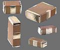
- Different designs of ceramic capacitors for electronics
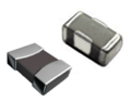
MLCC chip capacitors

Ceramic disc capacitor

Axial ceramic feed-through capacitor

High-voltage disc capacitor


The design for surface mounting, the MLCC chip capacitors as back-up or decoupling capacitors in digital circuits, has achieved great importance within the family of ceramic capacitors . This type of construction, in which many layers of metallized ceramic carriers are stacked on top of one another, is also found in the MLCC arrays, i.e. several MLCC capacitors in one housing and in X2Y-MLCC decoupling or feed-through capacitors. Ceramic disc capacitors, mostly designed for higher voltages, or special designs such as B. Ceramic bushing capacitors complete the range of applications in electronic devices. In addition, ceramic power capacitors in disc or barrel form for applications with high voltages of up to 100 kV or for very high electrical outputs can be found on the market.
Application classes
Ceramic capacitors for electronic devices are divided into application classes according to their different properties. This can lead to misunderstandings due to the coexistence of standards. In the European area, European standardization (EN), which also includes German standardization (DIN), has been overseen by the European Committee for Standardization for decades . These standards are harmonized internationally within the framework of the IEC . So far, however, the standards of the Electronic Industries Alliance (EIA) have mainly applied to the US . The association as such disbanded at the end of 2010, so it can be expected that the EIA standards will gradually become less important.
For the classification of ceramic capacitors according to application classes, however, the coexistence of two standards means that misunderstandings can arise. According to the standardization according to IEC 60384-8 / 9/21/22 there are two classes ( English "classes" ):
- Class 1 ceramic capacitors with high stability requirements
- Class 2 ceramic capacitors with high volume efficiency
In the 1950s to 1980s, “Class 3” stood for junction capacitors and is now obsolete.
According to EIA RS-198 there was the following classification until 2010:
- Class I, but also written as “Class 1”, ceramic capacitors with high demands on stability
- Class II or "Class 2", ceramic capacitors with high volume efficiency
- Class III or "Class 3", ceramic capacitors with higher volume efficiency than Class II and a typical change in capacitance of −22% to +56% over a temperature range of 10 ° C to 55 ° C.
- Class IV or "Class 4" also describes junction capacitors
In the following, however, the classification according to IEC 60384 is adopted.
Class 1 ceramic capacitors
| Sum formula |
Relative permittivity |
Temperature coefficient α in 10 −6 / K |
|---|---|---|
| MgNb 2 O 6 | 21st | −70 |
| ZnNb 2 O 6 | 25th | −56 |
| MgTa 2 O 6 | 28 | +18 |
| ZnTa 2 O 6 | 38 | + 9 |
| (ZnMg) TiO 3 | 32 | + 5 |
| (ZrSn) TiO 4 | 37 | ± 0 |
| Ba 2 Ti 9 O 20 | 40 | + 2 |

Class 1 ceramic capacitors have a relatively low permittivity independent of the field strength and are used in electrical circuits with high demands on frequency accuracy and low dielectric losses.
The starting material for class 1 ceramic capacitors is a mixture of finely ground granules of paraelectric base materials such as titanium dioxide (TiO 2 ) modified by adding Zn, Zr, Nb, Mg, Ta, Co and Sr, which later become the dielectric with the desired properties.
With the field strength-independent and relatively small relative permittivity (6 to 200) of class 1 ceramics, only ceramic capacitors with relatively small capacitance values and with a relatively small specific capacitance can be produced. The temperature behavior of the capacitance can be precisely produced through the composition of the ceramic aggregates, so that specific temperature gradients of the capacitance can be generated. This temperature behavior is also almost linear. The capacitance of class 1 ceramic capacitors has no material-related aging and shows almost no dependence of the capacitance value on the applied voltage. Class 1 ceramic capacitors also have very low electrical losses with loss factors of <0.5%. With these properties, class 1 ceramic capacitors are suitable for temperature compensation of connected components in resonance circuits with high demands on frequency accuracy and high quality such as e.g. B. in filters, resonant circuits or oscillators, and voltage-frequency converters.


The temperature dependency of class 1 ceramic capacitors is categorized in common usage according to the temperature coefficient in the industry by designations such as “NP0”, “N220”, etc. According to the international ( IEC ), whose standards are adopted by the European standard ( EN ), and the former US standards association EIA , this capacitor designation is replaced by a code that provides information about the course and tolerance of the temperature dependency.
The classification is carried out according to IEC 60384-8 / 21 using a two-digit code and a three-digit code according to EIA RS-198.
Class 1 ceramic capacitors can be manufactured with many different temperature coefficients α. Starting with the positive α of + 100 · 10 −6 / K, also “ ppm / K”, the material NP0 (“negative-positive-zero”) - or C0G - is of great technical interest. These ceramic capacitors have almost no temperature dependence of the capacitance (α = ± 0 · 10 −6 / K, α tolerance ± 30 · 10 −6 / K). This means that the temperature dependence of the capacitance value dC / C is less than ± 0.54% over a temperature range of −55… + 125 ° C. This is an ideal prerequisite for a very precise frequency response over a wide temperature range. In addition to these two mentioned, there are also a number of temperature coefficients with negative α values that can precisely counteract a positive temperature behavior of components connected in parallel with the capacitor. It goes without saying that class 1 ceramic capacitors, especially those with small α tolerances, are also supplied with very small delivery tolerances of the nominal capacity (see capacitance values and tolerances).
Coding of the temperature coefficient α of class 1 ceramic capacitors
| designation | Temperature coefficient α in 10 −6 / K |
IEC / EN code for α |
α tolerance in 10 −6 / K |
IEC / EN code for α tolerance |
lower class |
IEC / EN code |
EIA code |
|---|---|---|---|---|---|---|---|
| P100 | 100 | A. | ± 30 | G *) | 1B | AG | M7G |
| NP0 | ± 0 | C. | ± 30 | G *) | 1B | CG | C0G |
| N33 | - 33 | H | ± 30 | G *) | 1B | HG | H2G |
| N75 | - 75 | L. | ± 30 | G *) | 1B | LG | L2G |
| N150 | −150 | P | ± 60 | H | 1B | PH | P2H |
| N220 | −220 | R. | ± 60 | H | 1B | RH | R2H |
| N330 | −330 | S. | ± 60 | H | 1B | SH | S2H |
| N470 | −470 | T | ± 60 | H | 1B | TH | T2H |
| N750 | −750 | U | ± 120 | J | 1B | UJ | U2J |
| N1000 | −1000 | Q | ± 250 | K | 1F | QK | Q3K |
| N1500 | −1500 | V | ± 250 | K | 1F | VK | P3K |
| +140… −1000 | - | SL | - | - | 1C | SL | - |
| *) Code letter for α tolerance ± 15 · 10 −6 / K | |||||||
| Letter code for α [10 −6 / K] |
Numeric code for multiplier |
Letter code for tolerance |
|---|---|---|
| C: 0.0 | 0: -1 | G: ± 30 |
| B: 0.3 | 1: -10 | H: ± 60 |
| L: 0.8 | 2: -100 | J: ± 120 |
| A: 0.9 | 3: -1000 | K: ± 250 |
| M: 1.0 | 4: +1 | L: ± 500 |
| P: 1.5 | 6: +10 | M: ± 1000 |
| R: 2.2 | 7: +100 | N: ± 2500 |
| S: 3.3 | 8: +1000 | |
| T: 4.7 | ||
| V: 5.6 | ||
| U: 7.5 |
Class 2 ceramic capacitors
Class 2 ceramic capacitors have a high field strength-dependent permittivity, which leads to a non-linear temperature and voltage dependence of the capacitance value. They are used in areas in which higher capacitance values with good sieving and decoupling properties are required.

Class 2 ceramic capacitors are made from ferroelectric materials such as B. barium titanate (BaTiO 3 ) and suitable additives such as aluminum or magnesium silicates and aluminum oxides. These ceramics have a field strength-dependent, but very high relative permittivity (at room temperature: 200 to 14,000). This allows ceramic capacitors with high capacitance to be produced in very small sizes. They have a large temperature and voltage dependence of the capacitance. The behavior of the component is therefore non-linear and they age significantly. Class 2 ceramic capacitors also have another, sometimes undesirable property, microphony .
Class 2 capacitors have significantly higher capacitance values compared to class 1 capacitors due to their higher relative dielectric constants and are suitable for applications in which only a minimum value of the capacitance is important. Examples are buffering and filtering in power supplies, as well as coupling and decoupling of electrical signals. They are manufactured as MLCC capacitors with capacitance values from 1 nF to 100 µF.
Class 2 ceramic capacitors are divided into categories that provide information about the temperature range and the change in capacitance over the temperature range. The most widely used classification is based on EIA RS-198 using a three-digit code.
Some common grade 2 ceramics are
- X7R (−55 ° C / + 125 ° C, ΔC / C 0 = ± 15%),
- X6R (−55 ° C / + 105 ° C, ΔC / C 0 = ± 15%),
- Z5U (+10 ° C / +85 ° C, ΔC / C 0 = −56 / + 22%),
- Y5V (−30 ° C / +85 ° C, ΔC / C 0 = −82 / + 22%),
- X7S (−55 ° C / + 125 ° C, ΔC / C 0 = ± 22%) and
- X8R (−55 ° C / + 150 ° C, ΔC / C 0 = ± 15%).
Z5U and Y5V capacitors are mainly used in areas where it can be ensured that they are operated in the vicinity of normal conditions (23 ° C).
In addition, there is a coding according to IEC 60384-9 and IEC 60384-22 in the international and European area, which specifies similar properties, but with different letters and a different structure of the code.
In most cases, it is possible to recode the ceramic type coding according to EIA according to the IEC code, even if small deviations occur:
- X7R corresponds to 2X1
- Z5U corresponds to 2E6
- Y5V similar to 2F4 , deviation: ΔC / C 0 = + 30 / −80% instead of + 30 / −82%
- X7S similar to 2C1 , deviation: ΔC / C 0 = ± 20% instead of ± 22%
- X8R no IEC / EN coding available
Class 2 ceramic capacitors, which by themselves have a large dependence of the capacitance on the temperature and the applied voltage, also have a large delivery tolerance of the nominal capacitance (see capacitance values and tolerances).
Coding of the temperature coefficient α of class 2 ceramic capacitors
| Ceramic subclass code | Max. Change in capacity C / C 0 | Specified temperature range | ||
|---|---|---|---|---|
| at U = 0 | at U = U N | code | Area | |
| 2 B | ± 10% | + 10 / -15% | 1 | −55 ... +125 ° C |
| 2C | ± 20% | + 20 / −30% | 2 | −55 ... +85 ° C |
| 2D | + 20 / −30% | + 20 / -40% | 3 | −40 ... +85 ° C |
| 2E | + 22 / -56% | + 22 / -70% | 4th | −25 ... +85 ° C |
| 2F | + 30 / -80% | + 30 / −90% | 5 | (−10 ... +70) ° C |
| 2R | ± 15% | - | 6th | +10 ... +85 ° C |
| 2X | ± 15% | + 15 / -25% | ||
| Limit temperature | Change in capacitance over the temperature range | |
|---|---|---|
| lower | upper | |
| X = −55 ° C | 4 = +65 ° C | P = ± 10% |
| Y = −30 ° C | 5 = +85 ° C | R = ± 15% |
| Z = +10 ° C | 6 = +105 ° C | S = ± 22% |
| 7 = +125 ° C | T = −33 / + 22% | |
| 8 = +150 ° C | U = −56 / + 22% | |
| V = −82 / + 22% | ||
Class 3 ceramic capacitors

The classification into "class 3 capacitors" was created for junction capacitors in the 1950s . These are ceramic capacitors made of doped ferroelectric ceramic materials such. B. Strontium titanate with an extraordinarily high relative permittivity of up to 50,000. You can therefore have higher capacitance values than class 2 capacitors with the same structural volume. However, junction capacitors have a stronger non-linear dependence of the capacitance on the temperature and on the voltage, higher frequency-dependent losses and a strong aging compared to class 2 capacitors.
Barrier layer capacitors could only be manufactured flat as single-layer disc capacitors or round as tubular capacitors. With their relatively high capacitance values, they were to be found in many circuits as an alternative to smaller electrolytic capacitors until around the mid-1990s. However, since this technology is not suitable for the production of multilayer capacitors, and because ceramic multilayer capacitors can now produce higher capacitance values with comparable electrical properties than junction capacitors, they are no longer produced today (2013).
There has not been a standard for class 3 capacitors since the 1980s.
Ceramic multilayer chip capacitors (MLCC)

Multilayer ceramic chip capacitors ( English Multilayer Ceramic Capacitor, MLCC ) deserve special attention because this design on the used quantity ago today, is the most common design of ceramic capacitors.
Manufacturing process

A multilayer ceramic chip capacitor consists of a large number of individual ceramic capacitors that are layered on top of one another and contacted together in parallel via the connection surfaces. The starting material of all MLCC chips is a mixture of finely ground granules of paraelectric base materials such as titanium dioxide (TiO 2 ) or ferroelectric base materials such as barium titanate (BaTiO 3 ), modified by adding zirconium , niobium , magnesium , cobalt and strontium . A powder is made from these basic materials. The composition and size of the powder particles, which today go down to the size range of a few 10 nm, represent an important know-how of the manufacturers of ceramic capacitors.

These materials are pulverized and mixed together homogeneously. A thin ceramic film is drawn from a suspension of the ceramic powder with a suitable binder. This is first rolled up for further transport. Unrolled again, it is cut into sheets of the same size, which are screen-printed with a metal paste, the future electrodes. In an automatic process, these sheets are stacked in a controlled manner in the number of layers required for the capacitor and solidified by pressing. In addition to the relative permittivity of the ceramic, the number of layers on top of each other determines the later capacitance value of the MLCC chip. When layering, it must be ensured that the electrodes in the stack are alternately stacked slightly offset from one another, so that they can later be contacted on one side with the connection surfaces in a comb-like manner.
The layered and pressed stack is then divided into the individual capacitors. You will get your later size here. Maximum mechanical precision is required, for example, with size "0201" with dimensions of 0.5 mm × 0.3 mm in order to stack 50 or more printed layers on top of one another.
After cutting, the binder is first baked out of the individual capacitors. Then the burning process takes place. The ceramic powder is sintered at temperatures between 1200 and 1450 ° C and receives its final, predominantly crystalline structure. Only through this firing process do the capacitors obtain their desired dielectric behavior. The firing process is followed by cleaning and then the external metallization of the two electrodes. The inner electrodes are connected in parallel through this metallization on the end faces of the ceramic block. At the same time, the metallizations are the external electrical connection surfaces. After completion of this manufacturing process, a 100% final test of the electrical values and packaging for automatic further processing in a device production takes place.
development

With the advancing miniaturization of the last decades, especially in digital electronics, the MLCC chips required in the periphery of the integrated logic circuits had to become smaller and smaller. This was achieved by thinner and thinner layers of the dielectric. While the minimum layer thickness was 1 µm in 2005, individual manufacturers can now (2010) produce MLCC chips with layer thicknesses of just 0.5 µm. The field strength in the dielectric increases to a remarkable 35 V / µm. The manufacturers succeeded in downsizing these capacitors by making the ceramic powders used more and more fine-grained and thus the ceramic layers fired from them could be thinner and thinner. In addition, the manufacturing process became more and more precisely controllable, so that more and more of these thin ceramic layers could be stacked on top of one another.
In a report by Murata it is described how the capacitance of a Y5V MLCC capacitor in size 1206 was increased from 4.7 µF to 100 µF / 4 V in the period from 1995 to 2005 through ever thinner ceramic layers and more and more layers on top of each other could. In the meantime (2010) Taiyo Yuden introduced a 100 µF / 4 V and an X5R chip capacitor in size EIA 0805 (2mm × 1.25mm × 1.25mm). Other voltages have other sizes: 16V, EIA 1210 (3.2mm × 2.5mm × 2.5mm) and 6.3V, EIA 1206 (3.2mm × 1.6mm ×?,? Mm).
In the meantime (2016) MLCC is available up to 1000 µF in size EIA 3225 and 470 µF / 4 V in size 4.5mm × 3.2mm × 2.5mm.
Sizes
Ceramic multilayer chip capacitors are produced in standardized sizes, the dimensions of which came from the American and were therefore measured in the unit “inches”. From the dimensions (length “L” and width “W”) in the unit “inch”, the international code, which is still used today, was created. So z. For example, the designation "0603" is 0.06 "long and 0.03" wide.
This code and the metric equivalent of the usual sizes of ceramic multilayer chip capacitors as well as the dimensions in mm are shown in the following table. The table does not contain the height "H". This is generally not included because the height of MLCC chips depends on the number of ceramic layers and thus on the capacitance of the capacitor. Normally, however, the dimension H should not exceed dimension W.
| Dimensional drawing | EIA code (customs) |
Dimensions L × W mil × mil |
IEC / EN code (metric) |
Dimensions L × W mm × mm |
EIA code (customs) |
Dimensions L × W mil × mil |
IEC / EN code (metric) |
Dimensions L × W mm × mm |
||
|---|---|---|---|---|---|---|---|---|---|---|
| 01005 | 16 x 7.9 | 0402 | 0.4 x 0.2 | 1806 | 180 × 63 | 4516 | 4.5 x 1.6 | |||
| 015015 | 16 × 16 | 0404 | 0.4 x 0.4 | 1808 | 180 × 79 | 4520 | 4.5 x 2.0 | |||
| 0201 | 24 × 12 | 0603 | 0.6 x 0.3 | 1812 | 180 × 130 | 4532 | 4.5 x 3.2 | |||
| 0202 | 20 × 20 | 0505 | 0.5 x 0.5 | 1825 | 180 × 250 | 4564 | 4.5 x 6.4 | |||
| 0302 | 30 × 20 | 0805 | 0.8 x 0.5 | 2010 | 200 × 98 | 5025 | 5.0 x 2.5 | |||
| 0303 | 30 × 30 | 0808 | 0.8 x 0.8 | 2020 | 200 × 200 | 5050 | 5.08 x 5.08 | |||
| 0504 | 50 × 40 | 1310 | 1.3 x 1.0 | 2220 | 225 × 197 | 5750 | 5.7 x 5.0 | |||
| 0402 | 39 × 20 | 1005 | 1.0 x 0.5 | 2225 | 225 × 250 | 5664/5764 | 5.7 x 6.4 | |||
| 0603 | 63 × 31 | 1608 | 1.6 x 0.8 | 2512 | 250 × 130 | 6432 | 6.4 x 3.2 | |||
| 0805 | 79 × 49 | 2012 | 2.0 x 1.25 | 2520 | 250 × 197 | 6450 | 6.4 x 5.0 | |||
| 1008 | 98 × 79 | 2520 | 2.5 x 2.0 | 2920 | 290 × 197 | 7450 | 7.4 x 5.0 | |||
| 1111 | 110 × 110 | 2828 | 2.8 x 2.8 | 3333 | 330 × 330 | 8484 | 8.38 x 8.38 | |||
| 1206 | 126 × 63 | 3216 | 3.2 x 1.6 | 3640 | 360 × 400 | 9210 | 9.2 x 10.16 | |||
| 1210 | 126 × 100 | 3225 | 3.2 x 2.5 | 4040 | 400 × 400 | 100100 | 10.2 x 10.2 | |||
| 1410 | 140 × 100 | 3625 | 3.6 x 2.5 | 5550 | 550 × 500 | 140127 | 14.0 x 12.7 | |||
| 1515 | 150 × 150 | 3838 | 3.81 x 3.81 | 8060 | 800 × 600 | 203153 | 20.3 x 15.3 |

NME and BME electrode and contact material
- Influence of metallization (NME or BME) on the voltage dependence of X7R multilayer ceramic chip capacitors
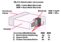
MLCC capacitors: electrode structure and connection surfaces of the metallization

Class 2 X7R MLCC capacitors: Influence of metallization on the voltage dependence of the capacitance


A particular problem in the production of ceramic multilayer chip capacitors was the sharp rise in prices for the metals used to metallize the electrodes and the connection surfaces at the end of the 1990s. Until then, the non-oxidizable noble metals silver and palladium were used in view of the high sintering temperatures of 1200 to 1400 ° C. There was also silver in the connection contact. Both metals are expensive and have a major impact on the final price of ceramic capacitors. This material composition also led to very good electrical properties of the class 2 capacitors and was called NME metallization (from noble metal electrode ). But it drove up the cost per component. The cost pressure led to the development of BME metallization (from English base metal electrode ). It contained the much cheaper materials nickel and copper .
The use of less inert base metals for the electrodes also means changing the ceramic materials used and the manufacturing processes. During sintering, the atmosphere must be controlled so that, on the one hand, the electrode material does not oxidize, but on the other hand, the lack of oxygen prevents oxygen vacancies from forming in the ceramic and thus making it conductive. This is not possible with the ceramic materials used in the conventional NME process.
The use of cheaper metals as electrode material for both internal and external electrodes has now become the standard for all leading manufacturers. For cost reasons, NME has been almost completely replaced by BME, both for class 2 and class 1 capacitors.
MLCC capacity ranges

The capacity of MLCC chips depends on the dielectric, the size and the required dielectric strength. The capacitance values start at around 1 pF. The maximum capacity value is determined by the current state of manufacturing technology. As a result, there has been a constant increase in the maximum capacity value for a given size from around 1990. The picture on the right shows the maximum capacitance for common class 1 and class 2 multilayer ceramic chip capacitors. The following tables list the currently maximum available capacitance values for the three ceramic types NP0 / C0G and X7R and the common nominal voltages for each size (status of the picture in the tables: April 2017, manufacturer AVX, Kemet and Murata).
| Nominal voltage |
Size, EIA code | ||||||||
|---|---|---|---|---|---|---|---|---|---|
| 01005 | 0201 | 0402 | 0603 | 0805 | 1206 | 1210 | 1812 | 2220 | |
| Dimensions in mm | |||||||||
| 0.4 x 0.2 | 0.6 x 0.3 | 1.0 x 0.5 | 1.6 x 0.8 | 2.0 x 1.25 | 3.2 x 1.6 | 3.2 x 2.5 | 4.5 x 3.2 | 5.7 x 5.0 | |
| Max. Capacity in the respective size | |||||||||
| 6.3V | 220 pF | - | - | 33 nF | - | - | - | - | - |
| 10 V | 220 pF | - | 4.7 nF | 33 nF | 100 nF | 100 nF | 220 nF | - | - |
| 16 V | 220 pF | - | 2.2 nF | 15 nF | 47 nF | 120 nF | 220 nF | - | - |
| 25 V | 220 pF | 1.0 nF | 2.2 nF | 47 nF | 47 nF | 120 nF | 220 nF | - | - |
| 50 V | 100 pF | 220 pF | 1.5 nF | 10 nF | 47 nF | 100 nF | 150 nF | 220 nF | 470 nF |
| 100 V | - | 100 pF | 1.0 nF | 4.7 nF | 22 nF | 100 nF | 100 nF | 150 nF | 330 nF |
| 250 V | - | - | 330 pF | 2.2 nF | 8.2 nF | 22 nF | 47 nF | 100 nF | - |
| 500 V | - | - | - | - | 820 pF | 4.7 nF | 10 nF | 22 nF | 47 nF |
| 630 V | - | - | - | - | 1.2 nF | 4.7 nF | 15 nF | 22 nF | 47 nF |
| 1000 V | - | - | - | - | 270 pF | 1.0 nF | 2.7 nF | 5.6 nF | 12 nF |
| 2000 BC | - | - | - | - | - | 270 pf | 680 pF | 1.5 nF | 3.9 nF |
| 3000 V | - | - | - | - | - | - | - | 390 pF | 1.0 nF |
| Nominal voltage |
Size, EIA code | ||||||||
|---|---|---|---|---|---|---|---|---|---|
| 01005 | 0201 | 0402 | 0603 | 0805 | 1206 | 1210 | 1812 | 2220 | |
| Dimensions in mm | |||||||||
| 0.4 x 0.2 | 0.6 x 0.3 | 1.0 x 0.5 | 1.6 x 0.8 | 2.0 x 1.25 | 3.2 x 1.6 | 3.2 x 2.5 | 4.5 x 3.2 | 5.7 x 5.0 | |
| Max. Capacity in the respective size | |||||||||
| 4 V | - | - | 2.2 µF | 2.2 µF | 22 µF | 100 µF | 100 µF | - | - |
| 6.3V | - | 0.1 µF | 2.2 µF | 10 µF | 22 µF | 47 µF | 100 µF | - | - |
| 10 V | 1.0 nF | 0.1 µF | 2.2 µF | 10 µF | 22 µF | 22 µF | 47 µF | - | - |
| 16 V | 1.0 nF | 0.1 µF | 2.2 µF | 4.7 µF | 10 µF | 22 µF | 22 µF | - | - |
| 25 V | - | 10 nF | 0.1 µF | 2.2 µF | 10 µF | 10 µF | 22 µF | - | 22 µF |
| 50 V | - | 1.5 nF | 0.1 µF | 0.47 µF | 4.7 µF | 4.7 µF | 10 µF | - | 10 µF |
| 100 V | - | - | 4.7 nF | 0.1 µF | 0.1 µF | 4.7 µF | 10 µF | 3.3 µF | 10 µF |
| 200 V | - | - | - | 10 nF | 56 nF | 0.15 µF | 0.22 µF | 1.0 µF | 1.0 µF |
| 250 V | - | - | - | 2.2 nF | 22 nF | 0.1 µF | 0.22 µF | 0.47 µF | 1.0 µF |
| 500 V | - | - | - | 3.9 nF | 22 nF | 68 nF | 0.1 µF | 0.22 µF | 0.47 µF |
| 630 V | - | - | - | 1.5 nF | 12 nF | 33 nF | 0.1 µF | 0.15 µF | 0.33 µF |
| 1000 V | - | - | - | 1.0 nF | 4.7 nF | 22 nF | 68 nF | 0.1 µF | 0.12 µF |
| 2000 BC | - | - | - | - | - | 2.2 nF | 6.8 nF | 10 nF | 22 nF |
| 3000 V | - | - | - | - | - | - | - | 1.2 nF | 15 nF |
Low ESL designs
- Comparison of the designs of an MLCC standard chip, an MLCC low ESL chip and an MLCC chip array

Standard design of an MLCC chip

Low ESL design of an MLCC chip

Design of an MLCC chip array


The resonance frequency of a capacitor is determined by the inductance of the component. The smaller this is, the higher the resonance frequency. In the area of its resonance frequency, a capacitor has the best screening properties against interference signals. Since the switching frequencies are getting higher and higher, especially in the field of digital signal processing , there is a need for decoupling or filtering capacitors for very high frequencies.
The inductive components in the structure of MLCC chips can now be reduced by a simple design change. In contrast to the standard MLCC, the electrodes of the stacked block are contacted on the long side with the connection surfaces. This reduces the path that the charge carriers have to cover on the electrodes, which leads to a reduction in the overall resulting inductance of the component. For the practical use of the capacitor this means z. B. that the resonance frequency of a 0.1 µF X7R capacitor in size 0805 increases from about 16 MHz to about 22 MHz when the MLCC chip is contacted as 0508 size with pads on the long side.
Another possibility is to design the capacitor as an MLCC array . By connecting several individual capacitors in parallel, their inductances are also connected in parallel. In addition, the internal ohmic losses of the individual capacitors are switched in parallel, which also reduces the resulting ESR value.
X2Y MLCC decoupling capacitor
- MLCC decoupling capacitor
X2Y-MLCC ceramic capacitors of different sizes

Structure of an X2Y MLCC capacitor

Circuit diagram of an X2Y MLCC capacitor

Connection of an X2Y-MLCC capacitor as a decoupling capacitor


As described above, a standard MLCC chip capacitor is produced from a stack of metallized ceramic carriers that are layered on top of one another and that are in contact with the terminal surfaces at the end faces. If further metallized ceramic carriers are now inserted between the ceramic carriers, which are transverse to the first stack and are contacted on both sides with the opposite lateral connection surfaces, a special chip capacitor is created, which, depending on the design, acts as a filter on signal lines as well as a decoupling capacitor Supply lines, can be used.
This special MLCC design with four connections per housing is known in the industry as an X2Y capacitor. It is used to filter high-frequency signals and to suppress interference from supply voltages from e.g. B. fast digital circuits . X2Y capacitors have been in use since the beginning of the 21st century.
Due to this design, and with appropriate placement on the circuit board, disruptive inductances in the supply lines are minimized. This is particularly interesting for use in fast digital circuits with clock rates of a few 100 MHz upwards. There, the decoupling of the individual supply voltages on the circuit board is difficult due to parasitic inductances of the supply lines with conventional ceramic capacitors and requires the parallel use of many conventional SMD ceramic capacitors with different capacitance values. Here, X2Y capacitors can replace up to five ceramic capacitors of the same size on the circuit board. However, this special design of ceramic capacitors is patented, which means that these components are still comparatively expensive (2008).
An alternative to the X2Y capacitors are capacitors with three connections.
Mechanical particularities
Ceramic is a brittle material; it breaks under comparatively low mechanical tensile loads. MLCC chips, which are surface-mounted components that are firmly seated on the circuit board between the soldering menisci, are exposed to such forces when the circuit board is mechanically deformed or subjected to impacts. That is why the resistance of MLCC chips to bending forces, the so-called “ flexural strength ”, is of particular importance for many applications
- MLCC chip capacitors with breakage and carrier bending test
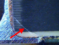
Micrograph of an MLCC chip capacitor with a break in the ceramic.

Simplified representation of a beam bending test of MLCC capacitors.


This flexural strength is determined by a standardized test, the " substrate bending test" . A test circuit board with a soldered-on MLCC chip is bent between two support points by means of a stamp by a path length of 1 to 3 mm. The path length depends on the requirements resulting from the application. The flexural strength of a capacitor is given if there is no break in the capacitor. Breaks are usually recognized by a change in the capacitance value in the bent state.
The flexural strength of the MLCC chip capacitors differs through the properties of the ceramic, the size of the chip and the construction of the capacitor. Without special design features, MLCC chips with class 1 ceramics (NP0 / C0G) achieve a typical flexural strength of 2 mm, while larger types of class 2 ceramics (X7R, Y5V) only achieve a flexural strength of around 1 mm. Smaller chips such as size 0402 achieve greater flexural strength values in all types of ceramic.
The flexural strength can be improved with special design features, especially the special design of the electrodes and the connection soldering surfaces.
The danger of a break in the ceramic of a standard MLCC chip capacitor lies in the fact that a short circuit can occur when the electrodes are shifted against each other. This can be prevented if the parts of the electrodes that are located in the covered area of the connection surface contact do not have an opposing electrode overlap. This is z. B. achieved through an "Open Mode Design" (OMD). In this construction, the opposing polarity electrode is so reduced that it is not touched by a break in the ceramic (manufacturer: AVX, KEMET).
- Different designs of ceramic capacitors for electronics
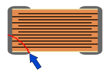
Standard MLCC:
If the ceramic breaks, the electrodes may shift, causing a short circuit.
Open-Mode-Design-MLCC:
If the ceramic breaks, only the capacity is reduced.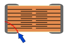
Floating-Electrode-Design-MLCC:
If the ceramic breaks, only the capacity is reduced.
Flex-Termination-MLCC:
A flexible contact layer (P) between the electrodes and the connection surfaces prevents the ceramic from breaking.


Something similar is achieved with the construction of the " Floating Electrode Design " (FED), also called "Multi Layer Serial Capacitors" (MLSC). In this construction, the electrodes inside the capacitor are cut in half on the respective ceramic substrate. The counter electrode is located on the ceramic carrier above it as a so-called "floating electrode" without an electrically conductive connection to the connection surfaces. This creates two internal capacitors that are connected in series. With both MLCC constructions, a break in the connection area of the ceramic cannot establish an electrical connection to the counter electrode. As a result, a break does not lead to a short circuit in the capacitor, but only causes a change in the capacitance value. However, both designs lead to larger designs compared to a standard MLCC version.
The same volume utilization as with a standard MLCC is achieved by introducing a flexible intermediate layer made of a conductive polymer between the electrodes and the connections, known as " Flexible Terminations " (FT-Cap) or "Soft Terminations", as they are e.g. B. is offered by AVX, MuRata, Kemet, Syfer and Holystone. With this construction, the rigid metallic connection soldering surface moves on the flexible polymer layer and can thus absorb the bending forces when bent without breaking the ceramic. This construction also leads to an increase in the flexural strength of class 2 capacitors up to the 3 mm deflection of the test circuit board required by the automotive industry.
Ceramic interference suppression capacitors

Ceramic capacitors are also of particular importance in the field of radio frequency interference (EMI, electromagnetic interference or RFI). Here, the wired ceramic interference suppression capacitors are used in large numbers because of their increased dielectric strength, the high impulse load capacity and their incombustibility.
In the context of miniaturization in industry, the surface-mountable chip designs are also becoming increasingly important for interference suppression capacitors. However, the ceramic SMD interference suppression capacitors (MLCC) must also meet all the requirements for high impulse dielectric strength and non-flammability in accordance with ENEC and UL approval. This means that the conditions for the tests and measurements of the electrical and mechanical parameters for the approval of the chip radio interference suppression capacitors are specified in the European area (ENEC) in the standard DIN IEC 60384-14 and must also meet these. In the meantime (2012) the industry is so advanced that MLCC suppression capacitors are offered by several manufacturers.
Ceramic power capacitors
- Different designs of ceramic capacitors for power electronics
High voltage disc capacitor

Ceramic bead capacitor

Ceramic barrel capacitor


Because of the easy malleability of the ceramic base material and the high dielectric strength of the ceramic, ceramic power capacitors can be found on the market in many different designs. Depending on the requirements, they are made of both class 1 and class 2 ceramics for high voltages in the range from 2 kV to 100 kV.

They are used as phase shifter capacitors in electrical high-voltage systems or transmitters for the generation of high frequencies with high power, in induction furnaces , in high-voltage pulse absorbers and in voltage doublers for high-voltage measuring devices.
The size of such power capacitors can be very large with high power losses. Ceramic high-voltage capacitors in barrel design are manufactured for extremely high power losses, even with built-in water cooling to dissipate the heat loss.
Ceramic power capacitors etc. are offered. a. by Denver, MorganElectroCeramics, Vitramon / Vishay and TDK.
Characteristic values
Equivalent circuit diagram


The electrical characteristics of capacitors are harmonized in the technical application in the international area by the framework specification IEC 60384-1, which appeared in Germany as DIN EN 60384-1 (VDE 0565-1) in March 2007. The electrical characteristics are described by an idealized series equivalent circuit diagram of a capacitor, in this case a ceramic capacitor.
In the adjacent figure are:
- C , the capacitance of the capacitor,
- R isol , the insulation resistance of the dielectric,
- R ESR , the equivalent series resistance, summarizes the ohmic losses of the component. This effective resistance is generally only called ESR (Equivalent Series Resistance),
- L ESL , the equivalent series inductance, it summarizes the inductance of the component, it is generally only called ESL (Equivalent Series Inductivity L ).
Impedance Z and ohmic losses (ESR, tan δ, quality Q)
Analogous to Ohm's law , where the quotient of direct voltage U DC and direct current I DC is equal to a resistance R , the quotient of alternating voltage U AC and alternating current I AC is :

Called alternating current resistance or impedance . It is the amount of the complex impedance of the capacitor at the selected measuring frequency. (In the data sheets of capacitors only the impedance, i.e. the amount of the impedance, is given).


If the series equivalent values of a capacitor are known, then the impedance can also be calculated using these values. It is then the sum of the geometric (complex) addition of the active and reactive resistors, ie, the equivalent series resistance ESR and the inductive reactance X L minus the capacitive reactance X C . The two reactances have the following relationships with the angular frequency ω :

which results in the following equation for the impedance :

(For the derivation of the sign convention used, see under Impedance ).
In the special case of resonance, in which the capacitive and inductive reactance are the same size ( X C = X L ), the impedance is equal to the ESR of the capacitor, the value in which all ohmic losses of the capacitor are combined.
For many ceramic capacitors, the loss factor tan δ is given in the data sheets instead of the ESR to specify the ohmic losses . It results from the tangent of the phase angle between the capacitive reactance X C minus the inductive reactance X L and the ESR. Neglecting the inductance ESL, the loss factor can be calculated with:

In the case of special, low-loss class 1 capacitors, instead of the loss factor, its reciprocal value, the "quality Q" or the "quality factor" is specified. This value relates to the bandwidth B at the resonance frequency f 0 and is calculated according to the equation:
- ,

where the bandwidth, defined as the frequency range at the limits of which the voltage level has changed by 3 dB compared to the mean, results from:
- .

with f 2 as the upper and f 1 as the lower limit frequency.
Capacity and capacity tolerance
| PREFERRED ferred rows |
tolerance | |||
|---|---|---|---|---|
| C R > 10 pF | ISIN book letter |
C R <10 pF | ISIN book letter |
|
| Class 1 ceramic capacitors | ||||
| E24 | ± 1% | F. | ± 0.1 pF | B. |
| ± 2% | G | ± 0.25 pF | C. | |
| ± 5% | J | ± 0.5 pF | D. | |
| E12 | ± 10% | K | ± 1 pF | F. |
| E6 | ± 20% | M. | ± 2 pF | G |
| Class 2 ceramic capacitors | ||||
| E6 | ± 20% | M. | - | - |
| E3 | −20 / + 50% | S. | - | - |
| −20 / + 80% | Z | - | - | |
Ceramic capacitors cover a very wide range of capacitance values from 0.1 pF to over 100 µF. The specified capacity value is called "nominal capacity CR". The capacitor is "named" after this capacitance value. The actual measured capacitance value must lie within the specified tolerance range around this nominal capacitance value.
The required capacity tolerance is determined by the area of application. For frequency-determining applications of class 1 capacitors, e.g. B. in resonant circuits , very precise capacitance values are required, which are specified with narrow tolerances. In contrast, class 2 capacitors for general applications such as B. for filter or coupling circuits from larger tolerance ranges.
Since the capacitance of ceramic capacitors is frequency-dependent and, in the case of class 2 types, also voltage-dependent, the measuring conditions are decisive in determining the exact capacitance value. According to the applicable standards, the following measurement conditions must be observed:
- Class 1 ceramic capacitors
- C R ≤ 100 pF with 1 MHz, measuring voltage 5 V.
- C R > 100 pF with 1 kHz, measuring voltage 5 V.
- Class 2 ceramic capacitors
- C R ≤ 100 pF with 1 MHz, measuring voltage 1 V
- 100 pF < C R ≤ 10 µF with 1 kHz, measuring voltage 1 V and
- C R > 10 µF with 100/120 Hz, measuring voltage 0.5 V
The different measuring frequencies for smaller and larger capacitance values are an adaptation to the main operating conditions. Smaller capacitance values are mostly operated with high or very high frequencies, larger capacitance values are more likely to be found in the range of lower frequencies.
The available capacity values are graded in the standardized " E series ". According to DIN, the following E series are preferred:
Individual manufacturers also supply nominal capacitance values according to E96, (96-C values / decade) or E48, (48-C values / decade).
Voltage dependence of the capacitance


Class 1 ceramic capacitors, which are made of paraelectric ceramic materials, show almost no dependence of the capacitance value on the applied voltage.
In contrast, class 2 ceramic capacitors have a dielectric constant that is dependent on the field strength. As a result, the capacity is dependent on the size of the applied voltage.
Class 2 ceramic capacitors have dielectrics made of ferroelectric materials, usually barium titanate with suitable additives. These change their dielectric constant with the size of the applied voltage. The closer the voltage approaches the nominal voltage, the lower the capacitance of the capacitor becomes. The change in capacitance can be up to 80% for some materials or nominal voltage values. With a thicker dielectric, this voltage dependency can be reduced within certain limits, but this is at the expense of the size.
The voltage dependence of the capacitance is also influenced by the type of electrode metallization. A BME metallization results in a greater voltage dependency of the capacitance compared to an NME metallization. The two adjacent images show the voltage dependency of capacitors with NME metallization. Ceramic capacitors with a BME metallization can have a significantly greater voltage dependency of the capacitance.
Temperature dependence of the capacity
The capacity is temperature dependent. The temperature coefficient is characteristic . It stands for the change in capacitance of a capacitor in relation to its nominal value when the temperature increases by 1 Kelvin . See also application classes .
Frequency dependence of the capacitance

Class 1 ceramic capacitors not only have a low, selectable dependence of the capacitance value on the temperature (see application classes), they also have a very low dependence of the capacitance on the frequency with which the capacitor is operated. In contrast, class 2 ceramic capacitors have a sometimes very strong dependence of the capacitance on the operating frequency. The picture on the right shows a typical frequency behavior of the capacitance of X7R and Y5V capacitors in comparison with class 1 NP0 capacitors.
Aging

The change in the electrical values of ceramic capacitors over time is called aging. In most cases the aging is related to the capacity value.
Class 1 ceramic capacitors show only very little aging. For the temperature dependencies from P 100 to N 470, the temporal inconsistency of the capacity is ≤ 1%, for the materials N 750 to N 1500 ≤ 2%.
Dielectrics made from ferroelectric materials such as barium titanate, from which the class 2 ceramic capacitors are made, exhibit a ferroelectric Curie temperature. Above about 120 ° C, the Curie temperature of barium titanate, the ceramic is no longer ferroelectric. Since this temperature is clearly exceeded when the ceramic is sintered in the manufacturing process, the ferroelectric property of the ceramic dielectric, the dielectric domains of parallel dielectric dipoles, is only formed again when the material cools down. However, due to the lack of stability of the domains, these areas disintegrate over time, the dielectric constant decreases and thus the capacitance of the capacitor decreases and the capacitor ages.
In the first hour after the ceramic has cooled below the Curie temperature, the decrease in capacity cannot be clearly defined, after which it follows a logarithmic law. This defines the aging constant as the decrease in capacity in percent during a decade of time, e.g. B. in the time from 1 h to 10 h.
Due to the aging of class 2 ceramic capacitors, it is necessary to specify an age for reference measurements to which the capacitance value relates. According to the applicable standard, this “age” is set at 1000 h. Capacitance measurements that are made earlier must be corrected with the aging constant determined for the ceramic.
The aging of class 2 ceramic capacitors essentially depends on the materials used. The higher the temperature dependency of the ceramic, the higher the aging rate over time. The typical aging rate of X7R ceramic capacitors is between 1.2 and 1.65% per time decade, whereby the maximum aging rate can be up to around 2.5% per time decade. The aging rate of Z5U ceramic capacitors is significantly higher. It can be up to 7% per decade of time.
Aging is reversible. The original capacity value can be restored by heating above the Curie point and then slowly cooling down (de-aging). For the user, the aging process means that the soldering process, especially with SMD capacitors and especially when soldering with lead-free solders, where the soldering temperatures are higher than conventional solders, resets the class 2 ceramic capacitors to a new condition. A waiting time should be observed after soldering if adjustment processes are required in the circuit.
Dielectric strength
| Type | nominal voltage | Test voltage |
|---|---|---|
| Ceramic multilayer chip capacitors (MLCC) |
U R ≤ 100 V | 2.5 U R |
| 100 V < U R ≤ 200 V | 1.5 U R + 100 V | |
| 200 V < U R ≤ 500 V | 1.3 U R + 100 V | |
| 500 V < U R | 1.3 U R | |
| Single layer ceramic capacitors |
U R ≤ 500 V | 2.5 U R |
| U R > 500 V | 1.5 U R + 500 V |
In the case of capacitors, a physically determined, definable dielectric strength, a breakdown voltage per thickness of the material, is usually specified for the respective dielectric material. This is not possible with ceramic capacitors. The breakdown voltage of a ceramic layer can vary by a factor of 10, depending on the composition of the electrode material and the sintering conditions. It requires great precision and mastery of the individual process parameters in order to keep the spread of the electrical properties within specifiable limits with the very thin ceramic layers customary today.
The dielectric strength of ceramic capacitors is specified using the term “nominal voltage U R ”. This means the DC voltage that may be applied continuously in the nominal temperature range up to the upper category temperature. This property is checked in that the relevant standards prescribe a "test voltage" with which the dielectric strength is checked.
In addition, the continuous voltage tests, with which the electrical properties are checked over a longer period of time (1000 to 2000 h), are carried out with increased test voltage (1.5 to 1.2 U R ) in order to ensure the "nominal voltage".
Impedance (Z)

The impedance of a ceramic capacitor is a measure of its ability to forward or divert alternating currents. The smaller the impedance, the better alternating currents are conducted. In the special case of resonance, in which the capacitive and inductive reactance are equal, the impedance reaches its smallest value. It then corresponds to the ESR of the capacitor.
The resonance frequency of a capacitor is determined by its capacitance value and its series inductance. The smaller the capacitance value, the higher the resonance frequency. If different capacitors have the same capacitance, the ESR is influenced by the structure of the capacitor. The more layers an MLCC chip capacitor, for example, needs to achieve a capacitance value, the smaller its ESR. Class 1 NP0 MLCC chips have lower ESR values than class 2 X7R chips because their dielectric has a lower dielectric constant and therefore more layers are required to achieve the same capacitance value.
The structural design of a capacitor shifts its resonance range to higher frequencies if its inductive components (ESL) are reduced by the design.
Ohmic losses, quality Q, loss factor tan δ and ESR
The ohmic losses of a ceramic capacitor are made up of the feed and discharge resistance, the contact resistance of the electrode contact, the line resistance of the electrodes and the dielectric losses in the dielectric, the amount of the losses being essentially determined by the dielectric.
| Temperature coefficient of the capacitor |
maximum loss factor |
|---|---|
| 100 ≥ α> −750 | tan δ ≤ 15 · 10 −4 |
| −750 ≥ α> −1500 | tan δ ≤ 20 · 10 −4 |
| −1500 ≥ α> −3300 | tan δ ≤ 30 · 10 −4 |
| −3300 ≥ α> −5600 | tan δ ≤ 40 · 10 −4 |
| ≤ −5600 | tan δ ≤ 50 · 10 −4 |
| For capacitance values <50 pF , larger values apply for the loss factor. |
|
| Nominal voltages of the capacitor |
maximum loss factor |
|---|---|
| ≥ 10 V | tan δ ≤ 350 · 10 −4 |
| For capacitance values <50 pF , larger values apply for the loss factor. |
|
In general, the ohmic losses of a capacitor are given with the loss factor tan δ. According to the applicable standards EN 60384-8 / -21 / -9 / -22, ceramic capacitors must not exceed the following loss factors (see tables).
With class 1 capacitors, which are intended for frequency-stable circuits, the reciprocal value, the "quality" Q or the "quality factor" , is often specified instead of the loss factor . A high quality value corresponds to a small bandwidth B at the resonance frequency f 0 of the capacitor. Since the shape of the impedance curve in the resonance range is steeper the smaller the ESR, a statement about the ohmic losses can also be made with the specification of the quality or the quality factor.
For larger capacitance values of class 2 capacitors, which are mainly used in power supplies, the manufacturer's data sheets usually specify the ESR instead of the loss factor. This emphasizes that ceramic capacitors have significantly lower values when comparing ohmic losses compared to electrolytic capacitors.
The ohmic losses of ceramic capacitors are frequency, temperature, voltage and, for class 2 capacitors, due to aging, also time-dependent, with the different ceramic materials showing varying degrees of changes in losses over the temperature range and over the operating frequency. The changes in class 1 capacitors are in the single-digit percentage range, while class 2 capacitors show significantly higher changes.
The dependencies of the ohmic losses can be explained as follows: Because the dielectric losses of ceramic capacitors at higher frequencies become greater with increasing frequency due to the ever faster polarization of the electrical dipoles, the losses in the capacitor increase with increasing frequency, depending on the type of ceramic. The ohmic losses are also dependent on the strength of the dielectric. Capacitors with higher dielectric strength and thicker dielectrics therefore have higher losses at the same frequency. The temperature also influences the ohmic losses in the capacitor. Because of the better mobility of the dipoles at high temperatures, the losses decrease with increasing temperatures.
Because of the frequency dependence of the ohmic losses, it is important to clearly define the measurement parameters for arbitrary measurements.
- For class 1 ceramic capacitors with capacitance values ≤ 1000 pF, the quality Q or the loss factor tan δ is specified at a measuring frequency of 1 MHz.
- For class 1 and class 2 ceramic capacitors with capacitance values of> 1000 pF to ≤ 10 µF, the loss factor is specified measured at 1 kHz
- For capacitors> 10 µF the loss factor or the ESR measured with 100/120 Hz is specified.
Measurements are made with an alternating voltage of 0.5 V / 1 V at room temperature.
AC load capacity
An alternating voltage or an alternating voltage superimposed on a direct voltage causes charging and discharging processes in the ceramic capacitor. An alternating current flows, which is colloquially also called ripple current . Due to the ESR of the capacitor, this leads to frequency-dependent losses that heat the component from the inside out. The resulting heat is released into the environment via convection and heat conduction. The amount of heat that can be released into the environment depends on the dimensions of the capacitor and the conditions on the circuit board and the environment.
The permissible alternating current load or the associated frequency-dependent effective alternating voltage of a ceramic capacitor is only rarely given in the respective manufacturer's data sheets. Since the electrical values of a ceramic capacitor are generally not influenced by a ripple current, only the heat generated in the capacitor is important for reliable operation. An alternating current flowing through the ceramic capacitor must therefore only be so large that its specified maximum temperature is not exceeded by the internally generated heat. The temperature difference between the ambient temperature and the upper category temperature therefore determines the size of the permissible alternating current load. This permitted temperature difference depends on the size of the capacitor.
Of course, the voltage associated with the alternating current must not exceed the maximum rated voltage of the capacitor. Exceeding the specified nominal voltage can destroy the capacitor.
Insulation resistance, self-discharge time constant
A charged capacitor discharges over time through the insulation resistance R isol of its dielectric. The self-discharge time constant τ isol results from the multiplication of the insulation resistance by the capacitance C of the capacitor .

The self-discharge time constant is a measure of the quality of the dielectric in terms of its insulating capacity and is specified in "s" (= seconds). Values between 100 and 1,000,000 seconds are common. The applicable EN standards specify the minimum values of the insulation resistance and the self-discharge time constant of ceramic capacitors for:
- SMD and wired ceramic capacitors class 1
- C R ≤ 10 nF, R i ≥ 10,000 MΩ
- C R > 10 nF, R i · CN ≥ 100 s
- SMD and wired ceramic capacitors class 2
- C R ≤ 25 nF, R i ≥ 4000 MΩ
- C R > 25 nF, R i · CN ≥ 100 s
The insulation resistance and the self-discharge time constant based on it are temperature-dependent. It is always relevant when a capacitor is used as a time-determining element (e.g. in a time relay) or for storing a voltage value e.g. B. is used in an analog memory.
The insulation resistance must not be confused with the insulation of the component from the environment.
Dielectric absorption, recharge effect
Once capacitors have been charged and are then completely discharged, they can then build up a voltage again without external influence, which can be measured at the connections. This recharge effect is known as dielectric absorption or dielectric relaxation.
While the capacitance of a capacitor is essentially defined by the space charge, atomic restructuring in the molecules of the ceramic dielectric also leads to a geometric alignment of the electrical elementary dipoles in the direction of the prevailing field. This alignment takes place with a much slower time constant than the space charge process of the capacitor and consumes supplied energy. Conversely, this alignment is lost just as slowly with the discharge of a capacitor and returns the energy released in the form of a space charge and thus a voltage on the capacitor. This recharged voltage can, even if the recharging effect is low, falsify measured values.
The dielectric effect of the dielectric absorption always counteracts a change in voltage and thus also causes the partial discharge of a capacitor that has just been charged. The difference between the time constant of the space charge process and the dipole alignment determines the size of the dielectric absorption and is proportional to each other.
Ceramic capacitors have a small, but not negligible, recharging effect. For class 1 capacitors it is about 0.3 to 0.6%, for class 2 X7R capacitors 0.6 to 1% and for class 2 Z5U capacitors 2.0 to 2.5%.
Piezo effect
All ferroelectric materials have a piezoelectricity , a piezo effect ( microphony ). It is based on the phenomenon that when certain materials are mechanically deformed, electrical charges occur on the surface , although these are very small even with particularly suitable materials.
Since the class 2 ceramic capacitors consist of ferroelectric base materials, an undesirable voltage can arise on the electrodes under certain circumstances when mechanical pressure is applied to the capacitor or when there are shock or vibration loads , which is very low, but with sensitive electronic circuits, for example in measuring devices, could lead to incorrect measurement results. For this reason, high-quality audio amplifiers use either class 1 ceramic capacitors, which consist of paraelectric base materials and have no piezo effect, or film capacitors (see also microphones ).
Due to the reversibility of the piezo effect (inverse piezo effect), when there is a high alternating current load (pulse switching) of the ceramic capacitor, sound can be partially heard through the capacitor and the circuit board.
Labelling
The marking of ceramic capacitors is no longer color-coded. If there is enough space, the capacitors should be marked with: nominal capacity, tolerance, nominal voltage, nominal temperature range (climate category), temperature coefficient and stability class, date of manufacture, manufacturer, type designation. Radio interference suppression capacitors must also be marked with the corresponding approvals, provided there is space for them.
Capacity, tolerance and date of manufacture can be marked with abbreviations according to EN 60062. Examples of a short designation of the nominal capacitance (picofarad): p47 = 0.47 pF, 4p7 = 4.7 pF, 47p = 47 pF
There are labeled and unlabeled multilayer ceramic chip capacitors.
standardization
The general definitions of the electrical values relevant for capacitors, the tests and test procedures as well as the measurement regulations for the tests are laid down in the basic specification
- IEC 60384-1 fixed capacitors for use in electronic devices - Part 1: Generic specification
Several framework specifications apply to ceramic capacitors, depending on their class and design. The tests and requirements that the respective ceramic capacitors must meet for approval are specified in:
- IEC 60384-8: Fixed capacitors for use in electronic equipment - Part 8: Sectional specification - Ceramic fixed capacitors, class 1
- IEC 60384-21: Fixed capacitors for use in electronic equipment - Part 21: Framework specification: Surface mount multilayer ceramic fixed capacitors, Class 1
- IEC 60384-9: Fixed capacitors for use in electronic equipment - Part 9: Sectional specification - Ceramic fixed capacitors, class 2
- IEC 60384-22: Fixed capacitors for use in electronic equipment - Part 22: Sectional specification: Surface mount multilayer ceramic fixed capacitors, Class 2
The named standards are published in Germany as DIN standards DIN EN 60384-8 / 21/9/22 . The corresponding DIN standard has been withdrawn for class 3 ceramic capacitors (junction capacitors).
Applications
The following table lists the most important properties and applications of ceramic capacitors of classes 1 and 2.
| class | properties | Areas of application |
|---|---|---|
| Class 1: Capacitors with a defined temperature coefficient |
|
Resonant circuits, filter circuits, temperature compensation, coupling and filtering in HF circuits. |
| Class 2: High dielectric constant capacitors |
|
Coupling, decoupling, radio interference suppression, buffering and filtering, snubber circuits, feed-through capacitors, power capacitors |
Advantages and disadvantages of ceramic capacitors
Advantages of ceramic capacitors
The electrical properties of capacitors can be adapted to the diverse requirements of electronic and electrical circuits by appropriate selection of different ceramic base materials with ceramic capacitors. A choice can be made between temperature- and frequency-stable electrical parameters, with relatively small capacitance values having to be accepted, or high capacitance values with, however, temperature- and voltage-dependent parameters.
Because of the easy malleability of the ceramic base material, ceramic capacitors can easily be made into almost any desired shape and size. This enables capacitors with dielectric strengths of up to 100 kV and more to be manufactured. Ceramic capacitors are only very flame-retardant and therefore, as interference suppression capacitors, offer an important prerequisite for use in safety-relevant applications. The larger wired designs are also relatively insensitive to overvoltages and overvoltage pulses. Ceramic capacitors in the form of SMD ceramic multilayer capacitors can be manufactured technically and inexpensively as surface-mountable components.
Class 1 ceramic capacitors are preferred in applications for frequency stable circuits, such as. B. resonant circuits, filter circuits, temperature compensation, coupling and filtering are used in HF circuits. They show small loss factors, high quality, little dependence of the capacity and the loss factor on the temperature and the frequency as well as almost no aging.
Class 2 ceramic capacitors offer relatively stable, low-loss capacitors with high current carrying capacity for applications in the field of power supplies. In particular, the surface-mountable ceramic capacitors called "MLCC" can replace plastic film or smaller electrolytic capacitors. Ceramic capacitors are subject to much less aging, especially compared to aluminum electrolytic capacitors with liquid electrolytes.
Disadvantages of ceramic capacitors
Surface-mountable ceramic capacitors (MLCC) with small sizes are more sensitive to overvoltage and high-energy overvoltage pulses, which can lead to a short circuit in the component. They are also very sensitive to mechanical stresses during assembly and mechanical bending of the circuit board as a result of vibration and shock loads. This can result in breaks in the ceramic and possibly short circuits. The thermal stress during soldering, especially when soldering with lead-free solders, can lead to breaks and short circuits on SMD ceramic capacitors.
With class 2 ceramic capacitors, microphones can occur under certain circumstances. It arises from electromagnetic coupling, which under certain circumstances can result in mechanical vibrations in the ceramic. The piezo effect of certain ceramics can then lead to the induced alternating voltages on the capacitors, known as "microphony".
The capacitance value of class 2 ceramic capacitors depends on the voltage. At higher operating voltages, the capacitance value decreases.
In the case of SMD ceramic capacitors, due to their very low internal ohmic losses when mounted on printed circuit boards, undamped resonance circuits with very high interference frequencies can arise with the supply conductor tracks.
Market data, manufacturers and products
Market leaders in the field of ceramic capacitors with market shares in the double-digit percentage range are: Murata, Samsung Electro-Mechanics (SEMCO), Taiyo Yuden. This is followed by a number of large, globally operating manufacturers with market shares in the single-digit percentage range: TDK / EPCOS, Kyocera / AVX, Phycomp / Yageo, Kemet, Walsin, Vishay / Vitramon, ROHM , EPCOS, Dover Technologies (Novacap, Syfer). (Data as of 2012)
The following table provides an overview of the product ranges of globally operating manufacturers in March 2008:
| Manufacturer | Available finishes | |||||
|---|---|---|---|---|---|---|
| tension | Capacitor type | |||||
| <1 kV | = 1 kV | Working wired |
decision sturgeon |
transit management |
performance processing |
|
| AVX / Kyocera Ltd. , ATC, American Technical Ceramics | X | X | X | X | - | - |
| Cosonic Enterprise | X | X | X | X | - | - |
| Dearborne | - | - | - | - | - | X |
| Dubilier | X | X | X | X | X | - |
| HolyStone | X | X | X | X | X | - |
| Hua Feng Electronics (CINETECH) | X | X | - | - | - | - |
| Johanson Dielectrics Inc. | X | X | X | X | - | - |
| KEKON | - | X | X | - | - | - |
| Kemet , Arcotronics, Evox Rifa | X | X | X | X | - | X |
| KOA Speer Electronics, Inc. | X | - | X | - | X | - |
| Morgan Electro Ceramics | - | - | X | - | - | X |
| Murata Manufacturing Co. Ltd. | X | X | X | - | X | - |
| NIC | X | X | X | X | - | - |
| NCC, Europe Chemi-Con | X | X | X | - | - | - |
| Novacap, Syfer | X | X | X | X | X | - |
| Prosperity Dielectrics Co. (PDC) | X | X | - | X | - | - |
| Samsung Electro-Mechanics Co. Ltd. | X | X | - | - | X | - |
| Samwha Capacitor Group | X | X | X | - | X | - |
| Taiyo Yuden | X | - | - | - | - | - |
| TDK - Epcos (TDK-EPC Corporation) | X | X | X | X | - | X |
| Tecate Group | X | X | X | X | - | - |
| Tusonix | - | X | X | X | X | - |
| Union Technology Corporation (UTC) | X | X | X | X | X | - |
| Vishay Intertechnology Inc. , Vitramon, CeraMite | X | X | X | X | X | X |
| Walsin Technology | X | X | X | X | - | - |
| Yageo , Phycomp | X | - | - | - | - | - |
| Yuetone | X | - | X | X | - | - |
literature
- Otto Zinke , Hans Seither: Resistors, capacitors, coils and their materials . 2nd Edition. Springer, Berlin 2002, ISBN 3-540-11334-7 .
- Electronics manual . Franzis Verlag, Munich 1983, ISBN 3-7723-6251-6 .
- D. Nührmann: The complete workbook electronics . New edition edition. Franzis Verlag, Munich 2002, ISBN 3-7723-6526-4 .
- Kurt Leucht: Capacitors for electronics engineers . Franzis Verlag, Munich 1981, ISBN 3-7723-1491-0 .
Web links
- Ceramic Capacitor Basics, Technical Brochure. (PDF; 289 kB) Novacap, accessed on December 5, 2011 (English).
- Sloka, Skamser, Phillips, Hill, Laps, Grace, Prymak, Randall, Tajuddin: Flexure Robust Capacitors. (PDF; 994 kB) Accessed December 5, 2011 .
- Multilayer Ceramic EMI Filters. (PDF; 241 kB) Syfer, accessed on December 5, 2011 .
- Capitance Change as Function of Applied Voltage. (PDF; 74 kB) Y5V Dielectric, NIC, accessed on December 5, 2011 .
- Basics of Ceramic Chip Capacitors. (PDF; 299 kB) Johanson, accessed on November 29, 2015 .
- POLYTERM Flexible SMD Termination for Multilayer Ceramic Capacitors (MLCC's). (PDF; 505 kB) Johanson, accessed on November 29, 2015 .
- Introduction to Safety Certified Capacitors. (PDF; 153 kB) Johanson, accessed November 29, 2015 .
- Capsite 2015 - Introduction to Capacitors (English)
Individual evidence
- ↑ a b c J. Ho, TR Jow, St. Boggs: Historical Introduction to Capacitor Technology . doi: 10.1109 / MEI.2010.5383924
- ↑ Telefunken TK 05 extinguishing spark / sound spark transmitter
- ↑ Extinguishing spark transmitter / sound spark transmitter Telefunken 1.5 TK
- ^ A b Mark D. Waugh: Design solutions for DC bias in multilayer ceramic capacitors . ( Memento of May 13, 2012 in the Internet Archive ) (PDF) Murata
- ^ Murata, Technical Report, Evolving Capacitors
- ↑ Advanced High Energy Capacitors . TRS Technologies; Retrieved February 21, 2008
- ^ W. Hackenberger, S. Kwon, E. Alberta: Advanced Multilayer Capacitors Using High Energy Density Antiferroelectric Ceramics . ( Memento of September 29, 2013 in the Internet Archive ) (PDF) TRS Technologies Inc.
- ↑ Ferroelectrics and antiferroelectrics, structure and properties . (PDF) University of Halle
- ↑ a b Ultra-high Voltage Ceramic Capacitors . ( Memento of July 9, 2007 in the Internet Archive ) (PDF; 56 kB) TDK; Retrieved February 21, 2008
- ↑ Chroma Technology Co., Ltd., CLASS III - General Purpose High-K Ceramic Disk Capacitors (PDF; 1.8 MB)
- ^ WS Lee, J. Yang, T. Yang, CY Su, YL Hu, Yageo: Ultra High-Q NP0 MLCC with Ag inner Electrode for Telecommunication Application. ( Page no longer available , search in web archives ) Info: The link was automatically marked as defective. Please check the link according to the instructions and then remove this notice. (PDF) In: Passive Components Industry , 2004, p. 26 ff.
- ↑ Specific capacity = capacity of a capacitor in relation to its construction volume
- ↑ Otto Zinke, Hans Seither: Resistors, capacitors, coils and their materials . 2nd Edition. Springer, Berlin 2002, ISBN 3-540-11334-7 .
- ↑ Intel Voices Concerns Over Quality of High Capacitance Ceramic Chip Capacitors
- ^ PCI, Murata's Summary and Outlook for Capacitors- January 2008 passivecomponentmagazine.com
- ↑ Taiyo Yuden Introduces World's First 100 μF EIA 0805 Size Multilayer Ceramic Capacitor online (PDF; 361 kB)
- ↑ TY [1]
- ↑ Yuki Nagoshi, Murata, AEI November 2009, Wielding Base Metal Yields Cheaper, Stable Class X2 Capacitors
- ↑ AVX, Low Inductance Capacitors (PDF; 373 kB)
- ↑ Multilayer Ceramic EMI-Filter, Syfer (PDF; 241 kB)
- ↑ X2Y Filters & Decoupling Capacitors . (PDF) Johanson
- ↑ X 2 Y Capacitor Technology
- ^ Three-terminal capacitor structure, Murata
- ↑ Bill Sloka, Dan Skamser, Reggie Phillips, Allen Hill, Mark Laps, Roy Grace, John Prymak, Michael Randall, Aziz Tajuddin: Flexure Robust Capacitors (PDF; 994 kB). CARTS, 2007.
- ↑ Murata, Chip Monolithic Ceramic Capacitors, Safety Standard Certified GA3 Series IEC60384-14 Class Y2, X1 / Y2 Type GF (PDF; 255 kB)
- ↑ Syfer's MLCC Safety Capacitors meet Class Y2 / X1 and X2 requirements
- ↑ Walsin, MULTILAYER CERAMIC CAPACITORS, Safety Certified X1 / Y2 Series (PDF; 609 kB)
- ^ Johanson AC Safety Capacitors, Type SC ceramic chip capacitors
- ^ M. Fortunato: Temperature and Voltage Variation of Ceramic Capacitors, or Why Your 4.7 µF Capacitor Becomes a 0.33 µF Capacitor . Maxim Integrated Products, Dec 04, 2012.
- ↑ Voltage Coefficient of Capacitors, Comparison & Solutions ( Memento from February 15, 2015 in the Internet Archive ) (PDF)
- ↑ Murata, data sheet X7R, 10µF, 25 V, GRM31CR71E106KA12 # (PDF)
- ↑ KW Plessner: Aging of the Dielectric Properties of Barium Titanate Ceramics . In: Proceedings of the Physical Society. Section B . tape 69 , 1956, pp. 1261-1268 , doi : 10.1088 / 0370-1301 / 69/12/309 .
- ↑ Takaaki Tsurumi, Motohiro Shono, Hirofumi Kakemoto, Satoshi Wada, Kenji Saito, Hirokazu Chazono: Mechanism of capacitance aging under DC-bias field in X7R-MLCCs . Springer Science + Business Media, LLC 2007.
- ^ Christopher England, Johanson dielectrics, Ceramic Capacitor Aging Made Simple
- ↑ Basics of ceramic capacitors (PDF) Technical brochure (English), Novacap (PDF; 289 kB)
- ↑ Are your military ceramic capacitors subject to the piezoelectric effect? ( Memento from June 19, 2012 in the Internet Archive ) In: Kemet FeedbackFAQ (information from Kemet on noise development).
- ^ Website of the manufacturer AVX
- ^ Website of the manufacturer American Technical Ceramics
- ↑ Web presence of the manufacturer Cosonic Enterprise Corp. Retrieved March 13, 2019 .
- ↑ Exxelia - About Exxelia - Exxelia Dearborn. In: exxelia.com. March 13, 2019, accessed March 13, 2019 .
- ^ Website of the manufacturer Dubilier
- ↑ Web presence of the manufacturer HolyStone ( Memento of the original from January 29, 2013 in the Internet Archive ) Info: The archive link was inserted automatically and has not yet been checked. Please check the original and archive link according to the instructions and then remove this notice.
- ↑ Website of the manufacturer Hua Feng Electronics
- ↑ Website of the manufacturer Johanson Dielectrics Inc.
- ↑ the manufacturer's website KEKON
- ↑ Website of the manufacturer Kemet
- ↑ Website of the manufacturer KOA Speer Electronics, Inc.
- ↑ Web presence of the manufacturer Morgan Electro Ceramics ( Memento of the original from June 15, 2012 in the Internet Archive ) Info: The archive link was inserted automatically and has not yet been checked. Please check the original and archive link according to the instructions and then remove this notice.
- ^ Website of the manufacturer Murata Manufacturing
- ^ Website of the manufacturer NIC
- ↑ Website of the manufacturer of capacitors and varistors from ECC - EUROPE CHEMI-CON. In: europechemicon.de. March 13, 2019, accessed March 13, 2019 .
- ↑ Web presence of the manufacturer Novacap ( Memento of the original from December 8, 2015 in the Internet Archive ) Info: The archive link was inserted automatically and has not yet been checked. Please check the original and archive link according to the instructions and then remove this notice.
- ↑ Web presence of the manufacturer Syfer
- ↑ Web presence of the manufacturer Prosperity Dielectrics Co.
- ^ Website of the manufacturer Samsung Electro-Mechanics Co. Ltd.
- ↑ Web presence of the manufacturer Samwha
- ^ Website of the manufacturer Taiyo Yuden
- ↑ Website of the manufacturer Home - TDK Electronics - TDK Europe. In: tdk-electronics.tdk.com. March 13, 2019, accessed March 13, 2019 .
- ^ Website of the manufacturer Tecate Group
- ↑ the manufacturer's website Tusonix
- ^ Website of the manufacturer Union Technology Corporation
- ↑ Web presence of the manufacturer Vishay Intertechnology Inc.
- ↑ Website of the manufacturer passivecomponent.com (PDF)
- ↑ Web presence of the manufacturer Yageo
- ↑ website of the manufacturer Yuetone