
Power capacitor
Power capacitors are electrical capacitors that are used in electrical energy engineering and power electronics as well as in high-voltage engineering . These capacitors, also known colloquially as high-voltage capacitors, come from the capacitor families of metal paper and polypropylene film capacitors . The power capacitors also include ceramic power capacitors , vacuum capacitors and SF 6 protective gas capacitors , which are mainly used in high-frequency technology .

General


Power capacitors are constructed in such a way that they can withstand higher electrical power and usually also higher electrical voltage . This higher electrical power and also the higher dielectric strength cannot be clearly defined. In the German-speaking world, the assignment can be explained from a historical point of view by the use of capacitors in electrics , electrical energy technology , high voltage and high frequency technology . These areas of application result in a lower power limit , which cannot be precisely defined, for power capacitors with a reactive power of around 200 var , for example for reactive current compensation capacitors for fluorescent lamp applications or for ceramic high-frequency capacitors for low-power transmitters . The upper performance limit of power capacitors is determined by the application. For harmonic filtering in high-voltage networks, for example, the maximum dielectric strength required is around 200 kV. High-frequency alternating currents of up to 1000 A can occur when high-power transmitters are in operation. Such upper limits can be mastered either by interconnecting several individual capacitors in larger, cuboid housings or by choosing a different capacitor technology.
The application largely determines the design of the power capacitors. Power capacitors are used for low-frequency alternating voltage or direct voltage operation and pulse direct voltage operation in low-voltage systems. These are metal paper or polypropylene plastic film capacitors with wound electrodes , built into large, round beakers. Several round buckets can be combined in cuboid housings. However, there are overlaps here that result from the expanding field of industrial power electronics . In the case of smaller and medium powers, the power capacitors are supplemented by smaller, round or cuboid plastic film capacitors, as they are known from electronics. For direct voltage applications, however, large aluminum electrolytic capacitors are used in addition to film capacitors , for example when they store larger electrical power for uninterruptible power supplies or frequency converters as backup or intermediate storage capacitors (DC-Link capacitors) .
For operation in high-frequency technology, on the other hand, ceramic capacitors, mostly in very special designs, as well as vacuum capacitors and SF 6 shielding gas capacitors are used. They are used in LC resonant circuits to generate high frequencies for high transmission powers in transmission technology, radar technology, in welding technology for welding plastics and in HF heating systems. SF 6 protective gas capacitors also serve as high-voltage capacitors in voltage dividers for precise measurement of high voltages or as bridge capacitors for measuring capacities and loss factors in high-voltage systems.
Foil power capacitors for direct or alternating voltage
The first industrially manufactured film power capacitors consisted of two paper strips of the appropriate width covered with metal foils , which were rolled up into a roll with another paper film, impregnated with an insulating oil and installed in a cup with soldered or screw connections. These paper capacitors were quite large and not particularly reliable.
The metal foils were later replaced by metal layers that were vapor-deposited onto the paper. These metal paper capacitors ( MP capacitors ) have self-healing properties, because in the event of a breakdown the material around the breakdown point evaporates, the cause of the breakdown is thus eliminated and the defect is, so to speak, "healed".
- Structure of power capacitors using paper in the roll and their common abbreviation

MP capacitor, paper capacitor with paper metallized on one side, winding impregnated with insulating oil

MPK capacitor, capacitor with mixed dielectric paper and polypropylene, with paper metallized on one side as an electrode carrier, winding impregnated with insulating oil

MKV capacitor, polypropylene capacitor with paper metallized on both sides as an electrode carrier, (paper is field-free) winding impregnated with insulating oil


MP power capacitors were used for high power, low frequency AC or DC voltage applications, as well as for pulse applications. In addition, MP capacitors were used in electrical devices and systems for reactive current compensation in gas discharge lamps and in factories with many electric drives. The impregnated paper has a dielectric strength of around 100 V / µm, a loss factor of around 70 · 10 −4 at 50 Hz and an insulation time constant of around 1000 s. Paper is polar and very hygroscopic. Before installing it in the cup, the moisture must therefore be removed from the roll in a vacuum drying system. To reduce the sensitivity to moisture and to increase the dielectric strength, the capacitor winding is also impregnated with an insulating oil. Until 1984, polychlorinated biphenyls (PCB) were also used to impregnate the paper. After 1984 all insulating oils for MP capacitors are free from chemicals containing PCBs.
- Structure of power capacitors with polypropylene films in the winding and their common abbreviations

MKP capacitor, also MKK capacitor, polypropylene capacitor with polypropylene foils metallized on one side, winding not impregnated (dry)

KP capacitor, polypropylene capacitor with metal coverings, winding not impregnated (dry)


With the development of plastics in organic chemistry, the capacitor industry began to replace the paper in paper capacitors with thinner and more stress-resistant plastic films after World War II. The plastics polyester ( polyethylene terephthalate , PET for short) and polypropylene (PP), for example, were first produced in large quantities at the beginning of the 1950s. Polypropylene has a dielectric strength of around 650 V / µm, at 50 Hz a loss factor of around 1 to 5 · 10 −4 , an insulation time constant of around 100,000 s and is virtually non-hygroscopic. Mainly because of the much smaller dissipation factor, which leads to the capacitor heating up at the high operating currents that flow through the power capacitors, polypropylene films have therefore become established in the field of power capacitors. Pure MP capacitors can therefore only be found today in radio interference suppression capacitors and in inexpensive designs with sufficient space. However, both for cost reasons (paper is cheaper than polypropylene) and for reasons of better adhesion of the metallization to paper compared to a polypropylene film, there are many variants with a mixed structure of plastic and paper film, especially in the case of power capacitors. The MKV capacitors are known here. In these capacitors, the winding consists of two paper foils coated on both sides which are separated from one another by a polypropylene foil as a dielectric. The paper foil is field-free and only serves as a carrier for the metallic electrodes.
particularities
At present, film power capacitors are mainly built with polypropylene films as the dielectric because of their significantly better electrical and thermal properties and because of their lower sensitivity to moisture. Such capacitors are usually manufactured in the form of wound foils with face-to-face contact that are installed in round cups. A special feature is the contact between the winding and the connection bolts, which is often a tensioned wire which, if there is overpressure in the cup, tears due to bulging of the lid and thus separates the capacitor from the network.

Several large round cup capacitors are often installed together in a cuboid housing for very high powers or for very high voltages, connected together and z. B. mechanically fixed by potting.
The connections of capacitors for high voltages must have sufficiently long paths on the surface because of the required resistance to leakage current . This is why high-voltage power capacitors often have connections with a corrugated ceramic surface.
safety rules
Power capacitors mostly work on dangerous electrical voltage. They have a low self-discharge and can carry high voltages for a very long time (months) after being switched off. Due to the low internal resistance, dangerous currents can occur if the contacts are touched, resulting in an electrical accident . So-called bleeder resistors (Bleederwiderstände) which are connected in parallel for security to the capacitors, limiting the discharge time to a few minutes.
However, capacitors can assume dangerous voltages again even after the short circuit has been completely discharged. The cause is changes in the charge distribution ( dielectric absorption ) occurring in the dielectrics . Power capacitors are therefore stored and transported short-circuited.
Electrical systems that contain high-voltage capacitors are subject to special safety rules and conditions. The reason is that dangerous voltages can occur in the electrical system even after it has been disconnected due to the charge stored in the capacitors. Such systems must comply with the valid regulations of the VDE, which are defined in several parts of the DIN-VDE standards 0560, see DIN-VDE standards part 5 .
Environmental aspects
Power capacitors were made in the past and are partly made today using insulating oil. Their disposal is therefore potentially hazardous to water. The highly toxic chlorodiphenyl or polychlorinated biphenyl (PCB) was also used as an insulating oil until around 1970 . Such capacitors were also used in household appliances (washing machines, spin dryers or voltage regulators) and require particularly careful handling and professional disposal.
application
Reactive current compensation

Reactive current compensation capacitors are alternating voltage capacitors that are permanently connected in parallel to the consumer or variably in reactive current compensation devices. They are phase shifting capacitors that improve the power factor (cos φ) ( reactive power compensation ). They are used in low-voltage systems to compensate for the inductive reactive current caused by conventional ballasts for fluorescent lamps , metal halide, sodium vapor lamps and high pressure mercury vapor lamps as well as electric motors. In addition, reactive current compensation capacitors are required in train drives and in inductive melting furnaces in the metal industry.
Reactive current compensation capacitors are mostly wound metallized plastic film capacitors , combined with impregnated paper (MPK capacitors) with polypropylene / impregnated paper as the dielectric , previously also metallized pure paper capacitors (MP capacitors). They are self healing.
For systems with a higher current load, the electrodes of the capacitors are also designed as metal foil coatings.
Damping capacitor
Damping capacitors, also known as snubber capacitors for medium current loads , are AC voltage capacitors that are connected in parallel to semiconductor components or inductive loads , sometimes in series with a resistor, in order to attenuate or reduce unwanted voltage peaks or voltage rise speeds that occur when the power semiconductors ( e.g. thyristor , triac or IGBTs ) are caused by the so-called carrier jam effect. The main properties of all damping capacitors are high dielectric strength and high peak current carrying capacity.
With lower current loads, damping capacitors are also used as RC elements with a resistor and capacitor in one housing.
Snubber capacitors without series resistance are often provided with large-area connections to improve the peak current capacity. Damping capacitors can be voltage-resistant up to 10 kV.
Nowadays, damping capacitors are mostly wound, metallized or plastic film capacitors provided with metal foil coatings with polypropylene as the dielectric .
Impulse or impulse capacitor

Impulse or pulse capacitors are DC voltage capacitors and are used to receive or deliver a strong, usually very short but high-energy current surge. The brief charging or discharging processes require correspondingly low- inductance connections; sometimes coaxial connection lines are necessary. Impulse or pulse capacitors are wound, metallized film capacitors with impregnated paper (MKP capacitor) or polypropylene as the dielectric.
Impulse or pulse capacitors are required in research and technology for the transient generation of strong magnetic fields, in plasma research and nuclear fusion, for the generation of high-energy flashes of light or X-ray, in cable fault location devices and in pulse welding machines.
Backup capacitor
Back-up capacitors (also called intermediate circuit capacitors ) are DC voltage smoothing capacitors after an AC voltage rectification, which smooth the rectified AC current and which can briefly emit high currents in the event of periodic peak current requirements and thus support a DC voltage network or consumers. Backup capacitors are z. B. required for frequency converters and actuators as well as in audio amplifiers .
Wound, metallized polypropylene film capacitors (MKP capacitor), film capacitors with metallized and impregnated paper as the field-free carrier for the electrodes and polypropylene as the dielectric (MKV capacitor) or aluminum electrolytic capacitors are used as backup capacitors .
Motor capacitor
Asynchronous motors require a rotating field at least to start up . In order to be able to operate them with a single-phase alternating voltage , a capacitor is used in capacitor motors and in the Steinmetz circuit , which with its phase shift generates an auxiliary phase and thus an electrical rotating field. For this purpose, one of the three winding connections is fed directly from the AC network, while a capacitor is connected in series to the second.
In the case of motor capacitors, a distinction is made between motor starting and motor operating capacitors:

- Starting capacitors
are only switched on at startup. Once the motor turns, the momentum of the rotor with the changing field of the alternating current ensures that it continues to run constantly. For this purpose, bipolar aluminum electrolytic capacitors with liquid electrolytes are usually used, which can be briefly connected to AC voltage. They must be switched off after startup. If the electrolytic capacitor is not switched off, there is a risk of explosion and / or the thin auxiliary winding of the capacitor motor designed for this purpose is thermally overloaded.
- Operating capacitors
stay connected all the time. This gives the motors a more favorable torque characteristic and can be smaller. The capacitors must be designed for a permanent load with an alternating voltage and the associated alternating current. The alternating voltage can be higher than the mains voltage depending on the load. Inexpensive motor operating capacitors are metal paper capacitors (MP capacitors), which, however, lead to larger sizes due to the relatively high electrical losses of the paper dielectric. This is why polypropylene film capacitors are mostly used today .
Connection diagrams of motor operating capacitors ( Steinmetz circuit )

|

|

|
| Delta connection | Star connection | Half-star connection |
Capacitor motors have only two windings, which can also be different when designed for an operating capacitor.
standardization

The standardization of power capacitors includes MP and polypropylene film power capacitors. They are strongly geared towards the respective application and since the safety of people and devices must be guaranteed when using power capacitors, the current DIN standards in Germany have also been published as VDE regulations. The basic terms and definitions for the application as well as for the tests of the electrical parameters of the power capacitors are published in the following standards:
- DIN EN 61071; VDE 0560-120: 2008-01 Capacitors for power electronics
- DIN EN 60252-1; VDE 0560-8: 2009-09 Motor capacitors - Part 1: General - Performance, testing and dimensioning - Safety requirements - Guidelines for installation and operation
- DIN EN 60110-1; VDE 0560-9: 1999-09 Power capacitors for inductive heating systems - Part 1: General
- DIN VDE 0560-10; VDE 0560-10: 1964-10 rules for capacitors; Part 10: Rules for high frequency power capacitors,
- DIN VDE 0560-11; VDE 0560-11: 1970-05 rules for capacitors; Part 11: Rules for capacitors from 600 V to smooth pulsating DC voltages
- DIN EN 60567; VDE 0370-9: 2006-05 Oil-filled electrical equipment - Sampling of gases and oil for the analysis of free and dissolved gases - Instructions
- DIN EN 60143-1; VDE 0560-42: 2004-12 Series capacitors for high voltage systems - Part 1: General
- DIN EN 60143-2; VDE 0560-43: 1995-12 Series capacitors for high voltage systems - Part 2: Protective devices for series capacitor batteries
- DIN EN 60143-3; VDE 0560-44: 1999-03 Series capacitors for high voltage systems - Part 3: Built-in fuses
- DIN EN 60252-2; VDE 0560-82: 2009-11 AC motor capacitors - Part 2: Motor starting capacitors
- DIN EN 60831-1; VDE 0560-46: 2003-08 Self-healing power parallel capacitors for AC systems with a nominal voltage of up to 1 kV - Part 1: General; Performance requirements, testing and sizing; Security requirements; Instructions for installation and operation
- DIN EN 60831-2; VDE 0560-47: 1997-09 Self-healing parallel power capacitors for AC systems with a nominal voltage of up to 1 kV - Part 2: Aging test, self-healing test and destruction test
- DIN EN 60871-1; VDE 0560-410: 2006-06 Parallel capacitors for AC high-voltage systems with a nominal voltage above 1 kV - Part 1: General
- DIN IEC 60871-2; VDE 0560-420: 1993-04 capacitors; Parallel capacitors for alternating voltage high-voltage systems with a nominal voltage above 1000 V; Part 2: Life test
- DIN EN 60931-1; VDE 0560-48: 2003-07 Non-self- healing parallel power capacitors for AC systems with a nominal voltage of up to 1 kV - Part 1: General; Performance requirements, testing and sizing; Security requirements; Instructions for installation and operation
- DIN EN 60931-2; VDE 0560-49: 1997-08 Non-self- healing parallel power capacitors for AC systems with a nominal voltage of up to 1 kV - Part 2: Aging and destruction test
- DIN IEC 60143-4; VDE 0560-41: 2008-07 Series capacitors for high voltage systems - Part 4: Thyristor- controlled series capacitors ,
- DIN EN 61921; VDE 0560-700: 2004-02 Power capacitors - capacitor banks for correcting the low voltage power factor;
- DIN EN 60931-3; VDE 0560-45: 1997-08 Non-self- healing parallel power capacitors for AC systems with a nominal voltage of up to 1 kV - Part 3: Built-in fuses
- DIN EN 61881; VDE 0115-430: 2000-08 Railway applications - Equipment on railway vehicles - Capacitors for power electronics ;,
- DIN IEC 62146-1; VDE 0560-50: 2003-12 Voltage equalization capacitors for high voltage AC circuit breakers,
- DIN 41900 high-frequency power capacitors with nominal voltages above 1 kV and reactive powers above 0.2 kVA; Technical values, date of issue: 1968-01
- DIN 48500 power capacitors; Technical delivery conditions, date of issue: 1974-01
High frequency and high voltage power capacitors
High-frequency power capacitors are capacitors, usually with larger dimensions, which are designed in high-frequency applications for nominal voltages above 1 kV and reactive powers above 200 VA. They are used in LC resonant circuits to generate high frequencies for high transmission powers in transmitter technology , radar technology , in welding technology for welding plastics and in HF heating systems. High-voltage power capacitors are used in high-voltage systems, e.g. They are used, for example, in high-voltage pulse absorbers and in voltage dividers for precise measurement of high voltages or as a bridge capacitor for measuring capacities and loss factors in high-voltage systems. These power capacitors include ceramic power capacitors, vacuum capacitors and SF 6 shielded gas capacitors .
Ceramic power capacitors
- Types of ceramic high frequency capacitors

High voltage disc capacitor.

Ceramic bead capacitor.

Ceramic barrel capacitor.


Ceramic power capacitors made from paraelectric class 1 ceramics have a dielectric constant that is independent of the field strength and a temperature curve of the capacitance that can be precisely produced and selected according to the respective application. This property, combined with low electrical losses, which are reflected in a high quality Q, make ceramic power capacitors suitable for temperature-compensated LC resonant circuits with higher power for generating high frequencies with high transmission power in transmission technology, radar technology, in welding technology Welding of plastics and in HF heating systems and in induction furnaces. For applications where higher capacitance values are required, e.g. B. in high-voltage systems and in voltage doublers for high-voltage measuring devices, class 2 ceramics are also used.
Ceramic materials are also easily malleable before firing. This enables the often very special designs that result from the respective application to be precisely manufactured. Annular beads on the edge of these capacitors increase the creepage distances for high voltages and enlarge the surface area for better dissipation of heat loss when there is a high current load. For extremely high power losses, cup-shaped capacitors can also be manufactured for water cooling.
Ceramic power capacitors are made of both class 1 and class 2 ceramics for high voltages in the range from 2 kV to 40 kV, depending on the requirements. Ceramic power capacitors and the like are manufactured. a. from the manufacturers: Dearborne, Morgan Electro Ceramics, TDK, Vishay Intertechnology Inc., Vitramon, CeraMite,
Vacuum capacitors
- Vacuum capacitors

Vacuum capacitor with glass housing

Sawn open vacuum capacitor with a fixed capacity with a view of the cylindrical electrodes
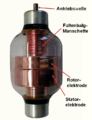
Variable vacuum capacitor with glass casing and information on the internal structure


A vacuum capacitor is an electrical capacitor in which a high vacuum with a gas pressure of about 10 −7 Torr (10 −5 Pa) is used as the dielectric. The low gas pressure of the vacuum reduces the probability of impact ionization of the air molecules (avalanche effect) squarely with the falling air pressure. This results in the very high dielectric strength of capacitors with a vacuum dielectric. Depending on the gas pressure, it lies between 20 and 500 kV / mm, is given on average at around 40 kV / mm and is therefore around ten times higher than for capacitors with an air dielectric at normal air pressure.
Vacuum capacitors are needed in high-frequency transmitters as resonant circuit capacitors and in applications where high voltages occur, e.g. B. in power LC resonant circuits for radio and television transmitters and in RF amplifier systems, in magnetrons for pulse shaping in the output circuit, in high-frequency welding devices and high-frequency drying systems, in plasma coating and plasma etching systems in the semiconductor industry and in nuclear magnetic resonance devices (MRI) as non-magnetizable capacitors. These applications require a very high dielectric strength and an extremely high current carrying capacity of the capacitors. Vacuum capacitors with dielectric strengths of up to 90 kV and current capacities of up to 1000 A are manufactured. Vacuum capacitors etc. are offered. a. from the manufacturers:
The main advantages of vacuum capacitors compared to ceramic power capacitors, which are specified with the same performance data, are the smaller dimensions, the significantly lower internal ohmic losses, which is expressed as a better quality factor Q, and the higher current carrying capacity of the capacitors. Vacuum capacitors are also self-healing. This means that they can easily withstand temporary overvoltages and overloads that would destroy other capacitors. Vacuum capacitors are manufactured in two designs, as fixed capacitors with a fixed capacitance value and as variable capacitors, the "variable vacuum capacitors", the respective capacitance of which is mechanically steplessly adjustable within defined limits. The setting of the variable vacuum capacitors, which is often required during transmission, is usually done using a controlled motor drive.
Vacuum capacitors consist of two concentrically arranged cylindrical electrodes with usually several cylinders mounted on a base plate. In the case of capacitors with a fixed capacitance value, these cylinder electrodes are pushed into one another concentrically without touching one another. In vacuum capacitors with adjustable capacitance values, a cylindrical rotor electrode is rotated concentrically into a stator electrode. Due to the cylindrical design of the electrodes, maximum volume utilization of the likewise round, hermetically sealed housing is achieved. Glass or a special ceramic is used as the material of the surrounding housing. As is customary in tube technology, the condenser is evacuated and sealed with suitable pumps.
SF 6 insulated capacitors
The SF 6 capacitors have a construction that is very similar to the vacuum capacitors. These capacitors use the inert gas sulfur hexafluoride (SF 6 ) with a gas pressure of 300 to 700 kPa as a dielectric. Because of its high dielectric strength, high ionization energy and the ability to bind free electrons, sulfur hexafluoride is also used as an insulating gas in medium and high voltage technology. However, its low dielectric loss factor is also decisive for its use in high-frequency power capacitors.
SF 6 capacitors are manufactured as fixed capacitors and also as variable, mechanically steplessly adjustable capacitors. The setting, which is often required during transmission, is usually done with electric motors. They are used in medium and long wave transmitters to correct the transmitter tuning, have adjustable maximum capacities of 50 to 5000 pF, have test voltages of up to 80 kV and can withstand currents of up to 800 A.
SF 6 capacitors are also used in voltage dividers for the precise measurement of high voltages or as a bridge capacitor for measuring capacities and loss factors in high voltage systems. These capacitors are offered with capacitance values up to 100 pF and with dielectric strengths up to 800 kV.
Manufacturers and Products
The following table provides an overview of the product ranges of global manufacturers of power capacitors (excluding vacuum and protective gas capacitors, as of July 2008):
| Available finishes | Snubber / impulse |
To shine- | Engine operating |
DC link PFC |
Single phase AC |
Three phase AC |
HF ceramic |
|---|---|---|---|---|---|---|---|
| Manufacturer | Capacitors | ||||||
| FIG | No | No | No | Yes | Yes | Yes | No |
| Advanced Components | Yes | No | No | Yes | Yes | No | No |
| AVX / Kyocera Ltd. | No | No | No | Yes | No | No | Yes |
| Aerovox | No | Yes | Yes | Yes | Yes | Yes | No |
| Amber Capacitors | No | Yes | Yes | No | Yes | No | No |
| Comar Condensatori SpA | No | Yes | Yes | No | Yes | Yes | No |
| Condenser Dominite | No | No | No | No | Yes | Yes | No |
| Dearborne | No | No | No | No | No | No | Yes |
| DUCATI Energia SPA | No | Yes | Yes | Yes | Yes | Yes | No |
| Electrocube | Yes | No | Yes | No | Yes | No | No |
| ELECTRONICON | Yes | Yes | Yes | Yes | Yes | Yes | No |
| FACON SPA | No | No | Yes | Yes | Yes | No | No |
| FRAKO | No | No | No | Yes | Yes | Yes | No |
| FTCap | No | No | Yes | Yes | Yes | No | No |
| GE capacitors | Yes | No | No | Yes | Yes | Yes | No |
| HIGH ENERGY Corp. | Yes | No | No | Yes | Yes | No | No |
| ICAR | Yes | Yes | Yes | Yes | Yes | Yes | No |
| Jianghai | Yes | No | Yes | Yes | Yes | Yes | No |
| KBR GmbH | No | No | No | Yes | Yes | Yes | No |
| Morgan Electro Ceramics | No | No | No | No | No | No | Yes |
| NWL | Yes | No | No | Yes | Yes | Yes | No |
| Norfolk Capacitors | Yes | No | No | Yes | Yes | Yes | No |
| Samwha Capacitor Group | No | No | Yes | Yes | Yes | Yes | No |
| Shizuki Electronic CO | Yes | No | Yes | No | Yes | No | No |
| TDK Epcos | Yes | Yes | Yes | Yes | Yes | Yes | No |
| Tobias Jensen Production | Yes | No | Yes | No | Yes | No | No |
| Vishay Intertechnology Inc. , Vitramon, CeraMite | Yes | No | No | Yes | Yes | Yes | Yes |
| WIMA CAPACITORS | Yes | Yes | No | Yes | No | No | No |
Individual evidence
- ↑ PCB leaflet of the Central Association of Electrical and Electronics Industry eV (ZVEI) PDF
- ↑ Beuth-Verlag, search: power capacitors [1]
- ↑ Source (40 kV DC, 25 kV AC): Ultra-high Voltage Ceramic Capacitors, TDK, PDF ( Memento of the original from July 9, 2007 in the Internet Archive ) Info: The archive link was inserted automatically and has not yet been checked. Please check the original and archive link according to the instructions and then remove this notice.
- ↑ Archived copy ( memento of the original from June 2, 2015 in the Internet Archive ) Info: The archive link was inserted automatically and has not yet been checked. Please check the original and archive link according to the instructions and then remove this notice.
- ↑ Archived copy ( memento of the original from June 15, 2012 in the Internet Archive ) Info: The archive link was inserted automatically and has not yet been checked. Please check the original and archive link according to the instructions and then remove this notice.
- ↑ [2]
- ↑ [3]
- ↑ Properties of the vacuum dielectric, Jennings, [4]
- ↑ Comet Company, [5]
- ↑ Omnicor (Meiden), archived copy ( memento of the original from May 3, 2014 in the Internet Archive ) Info: The archive link was inserted automatically and has not yet been checked. Please check the original and archive link according to the instructions and then remove this notice.
- ↑ Greenstone, USA, archived copy ( memento of the original from July 25, 2008 in the Internet Archive ) Info: The archive link was inserted automatically and has not yet been checked. Please check the original and archive link according to the instructions and then remove this notice.
- ↑ WVS, archived copy ( Memento of the original from January 20, 2009 in the Internet Archive ) Info: The archive link was inserted automatically and has not yet been checked. Please check the original and archive link according to the instructions and then remove this notice.
- ↑ WVS-Technology, Condis Compressed Gas Capacitors, X-Cap: Archived copy ( Memento of the original from January 16, 2009 in the Internet Archive ) Info: The archive link was inserted automatically and has not yet been checked. Please check the original and archive link according to the instructions and then remove this notice.
- ↑ HIGHVOLT Prüftechnik Dresden GmbH, [6]
- ^ Soken, [7]
- ↑ Samgor, [8]
- ↑ Web presence of the manufacturer ABB Archived copy ( Memento of the original from August 27, 2014 in the Internet Archive ) Info: The archive link was inserted automatically and has not yet been checked. Please check the original and archive link according to the instructions and then remove this notice.
- ↑ Website of the manufacturer Advanced Components [9]
- ↑ Web presence of the manufacturer AVX / Kyocera AVX
- ↑ Web presence of the manufacturer Aerovox [10]
- ↑ Website of the manufacturer Amber Capacitors [11]
- ↑ Web presence of the manufacturer Comar Condensatori SpA [12]
- ↑ Web presence of the manufacturer Condensator-Dominit [13]
- ↑ Web presence of the manufacturer Dearborne Archived copy ( Memento of the original from June 2, 2015 in the Internet Archive ) Info: The archive link was inserted automatically and has not yet been checked. Please check the original and archive link according to the instructions and then remove this notice.
- ↑ Website of the manufacturer Ducati [14] ( page no longer available , search in web archives ) Info: The link was automatically marked as defective. Please check the link according to the instructions and then remove this notice.
- ^ Website of the manufacturer Electrocube [15]
- ↑ Web presence of the manufacturer Electronicon EKG
- ↑ Website of the manufacturer Facon [16]
- ↑ Website of the manufacturer FRAKO [17]
- ↑ website of the manufacturer FTCap [18]
- ↑ Web presence of the manufacturer GE Capacitors Archived copy ( Memento of the original from July 27, 2008 in the Internet Archive ) Info: The archive link was inserted automatically and has not yet been checked. Please check the original and archive link according to the instructions and then remove this notice.
- ↑ Website of the manufacturer HIGH ENERGY Corp [19]
- ^ Website of the manufacturer ICAR [20]
- ^ Website of the manufacturer ICAR [21]
- ↑ Website of the manufacturer KBR [22]
- ↑ Website of the manufacturer Morgan Electro Ceramics Archived copy ( Memento of the original from June 15, 2012 in the Internet Archive ) Info: The archive link has been inserted automatically and has not yet been checked. Please check the original and archive link according to the instructions and then remove this notice.
- ^ Website of the manufacturer NWL [23]
- ↑ Website of the manufacturer Norfolk Capacitors [24]
- ↑ Web presence of the manufacturer Samwha [25]
- ↑ Web presence of the manufacturer Shizuki [26]
- ↑ Website of the manufacturer TDK Epcos [27]
- ↑ Website of the manufacturer Jensen [28]
- ↑ Web presence of the manufacturer Vishay [29]
- ↑ Web presence of the manufacturer WIMA [30]