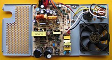
Single ended flux converter
The single-ended flux converter ( English Forward Converter ) is an embodiment of a galvanically isolated DC voltage converter , which is characterized in that the energy transfer takes place exclusively in the conducting phase of the individual switching component. Applications of this converter are, for example, switched-mode power supplies .
In contrast to flyback converters , which are particularly suitable for low powers , single-ended flux converters are used for powers from around 100 watts up to around 500 W, because they have a better degree of efficiency . Push-pull flux converters are used for higher outputs .
function

The converter is supplied with the DC voltage U E on the left, as simplified to the essential components in the sketch opposite . In the application area of switched-mode power supplies, this voltage is typically the rectified mains voltage of around 230 V, which corresponds to a smoothed DC voltage of around 325 V after rectification. In practical circuits, the switch S is designed as a switching transistor which is controlled by a control unit (not shown) with switching frequencies of a few 10 kHz to a few 100 kHz and different, since load-dependent, pulse widths.
The transformer Tr is used for galvanic isolation and converts the input voltage to a voltage on the secondary side according to the number of turns ratio. The rectification on the secondary side consists of the diode D 1 , followed by a circuit part which is largely identical to the down converter which is not galvanically separated . This part of the circuit is used to convert to the final DC output voltage U A for the consumers connected to the terminals on the outside on the right. This step-down converter consists of the freewheeling diode D 2 , the storage inductor L and the smoothing capacitor C, which is connected in parallel to the load.
The output voltage is load-dependent and has to be regulated via a feedback (not shown in the figure) that affects the pulse width of the switch control.
The converter is characterized by two states, which are determined by the state of one switch S (hence "single-ended"):
Leading state
With the switch closed S , a current flows through the primary winding of the transformer Tr and a translated to the reciprocal of the current through the turns ratio output-side diode D 1 and the storage inductor L . In this state, the diode D 2 is switched in the blocking direction and blocks. The current increases linearly as a magnetic field builds up in the storage choke. The capacitor C is charged. Since the energy transport from the primary to the secondary side of this converter happens in the lead phase, it belongs to the group of flux converters.
This state is held for a certain time t on , after which the switch S opens and the converter goes into the blocking state.
Lock state
When switch S is open, D 1 blocks because the secondary voltage reverses. The current through the storage choke L is constant and flows in the blocking phase via the then conductive D 2 . Together with the capacitor C , the output voltage U A is kept constant , apart from a small residual ripple (ripple).
This state is held for a certain time t off , after which the switch S closes and the cycle begins again with the conductive state.
With single-ended flux converters, the magnetizing current must be kept as small as possible and in this greatly simplified example is converted into heat loss in the blocking phase, since the primary-side current only ever flows in one direction and this leads to a direct current build-up in the transformer. A small magnetizing current can be achieved with core material with a high permeability number and by avoiding an air gap. The core halves of a flux converter are flat-ground, pressed together with clamps without a gap, which are processed without contamination on the support surfaces.
At a given operating frequency, the magnetization energy can also be reduced by increasing the number of turns, but this should be avoided in the interest of lower copper losses. To improve the efficiency, the transformer of the single-ended flux converter is therefore usually provided with an additional demagnetization winding.
Degaussing winding
The additional winding N2 in the adjacent circuit diagram serves to demagnetize the transformer core in the blocking phase and feeds the energy stored in the transformer back into the supply voltage or C1 via the diode D1. If the primary winding N1 and the demagnetizing winding N2 have the same number of turns, the ratio between conducting and blocking phases (pulse width ratio) is limited to a maximum of 50%.
The demagnetization winding N2 and D1 are not absolutely necessary for the function, but they increase the efficiency and reduce the voltage load on the switching transistor T1. As an alternative to such a winding, the magnetization energy of the transformer can safely be thermally dissipated using a flying-start circuit made up of a diode, resistor and capacitor or, in borderline cases, only with the avalanche breakdown of the MOSFET .
Push-pull flux converters such as the half and full bridge flow converters do not require their own demagnetization winding, but their pulse width ratio is generally limited to 50%.
literature
- Otmar Kilgenstein: Switching power supplies in practice . 3. Edition. Vogel Fachverlag, 1992, ISBN 3-8023-1436-0 .
- Heinrich Hübscher: Electrical engineering, training in communication electronics 2: Information technology, office information electronics. Westermann, Braunschweig 1992, ISBN 3-14-221430-5 .

