Optocoupler
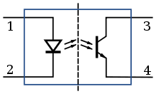
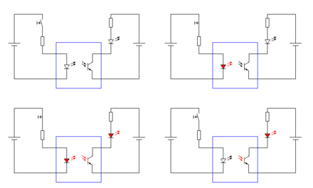
An optocoupler is a component of optoelectronics and is used to transmit a signal between two electrically isolated circuits . It usually consists of a light emitting diode (LED) or laser diode (LD) as an optical transmitter and a photodiode or a phototransistor as an optical receiver. The transmitter and receiver components are optically coupled to one another and housed in a housing that is opaque from the outside.
With optocouplers, both digital and analog signals can be transmitted. A distinction must be made between optocouplers and semiconductor relays , which can contain an optocoupler as a component for galvanic separation and are primarily used in electrical power engineering. Fork couplers and light barriers differ from optocouplers because they do not have a housing that is impervious to light from the outside and were not built for optical scanning applications.
history
The first optocouplers were made in 1963 by Ivars G. Akmenkalns et al. Developed by the company IBM and were resistive optocouplers, which in the first versions used smaller incandescent lamps or glow lamps as a transmitter element and a photo resistor as a receiver element in an opaque metal housing. In 1977 the lamps were replaced by light-emitting diodes and are used, among other things, in audio technology, e.g. B. in guitar amplifiers , used to control the characteristic of amplifiers. Resistive, d. H. Optocouplers working with photoresistor have a low cut-off frequency of 1… 200 Hz.
Since around 1972, optocouplers have been offered as electronic components in housings that are similar to those of chip housings , such as the dual in-line package (DIP). Elongated housing designs are also manufactured for high insulation voltages from around 4 kV . For safe mains separation, optocouplers are sometimes manufactured with a larger spacing of the connections in order to be able to maintain a creepage distance of 8 mm between the solder pads on printed circuit boards . The creepage distance under the optocoupler can also be extended with a slot if the spacing between the solder pads is insufficient.
construction
Either the sender and receiver are directly opposite each other ( English face-to-face design ) or are on one level ( English coplanar design ). In the latter case in particular, the light beam is transmitted by reflection, similar to the optical waveguide .
Light-emitting diodes or laser diodes are used as transmitters , which work in the optimal reception range of silicon-based receivers (around 850 nm wavelength). Phototransistors or photodiodes are used as receivers .
So-called PhotoMOS relays use a series connection of photodiodes, which are operated as photo elements, i.e. in the photovoltaic area, in order to switch MOSFETs with the voltage ; see also semiconductor relays. This means that small and large direct and alternating currents can be switched.
Optocouplers can be designed as triacs and function as optotriac or phototriac or can be connected together with triacs and thyristors . This provides a semiconductor relay ( English Solid State Relay ) for switching AC mains voltage.
So-called reflex couplers have outwardly directed transmitters and receivers and are used to detect nearby reflective surfaces. They are designed for print assembly.
The external light-independent reflex sensors available for automation are housed in an industrial housing together with the electronics and switching stages required for modulation.
Characteristic values
For analog optical couplers which are direct current transmission ratio ( English current transfer ratio , CTR) to the ratio between input and output current at DC signals or low signal frequencies. Depending on the receiver, the values are between 0.1… 0.5% (photodiode), 2… 120% ( phototransistor ) and 1,000… 15,000% (with Darlington transistor ). This value is considerably dependent on the current, especially when using phototransistors. Furthermore, it is temperature-dependent and decreases as the component ages. A reduction in brightness of more than 50% for the light-emitting diode due to aging is considered a fault. With digital optocouplers, no CTR is specified, but a minimum LED current that is required to change the level at the output.
The insulation voltage depends on the distance and arrangement of the transmitter and receiver, the insulation material and the distance between the connections. Usual insulation voltages are 200 V, 500 V, 1.5 kV, 2.5 kV, 4 kV or 5 kV, in special cases up to 25 kV.
The insulation resistance between the input and the output is very high and is up to 10 13 Ω .
The current of conventional optocouplers is 50 mA through the infrared LED in order to fully control the phototransistor. Seldom built optocouplers for a control current of up to 10 mA use an integrated Darlington transistor for this .
The cut-off frequency is the highest working frequency at which an optocoupler can still work. Depending on the type, this characteristic value is between a few kHz and a few GHz. Optocouplers with photo transistors have a cut-off frequency in the lower range, essentially limited by the slow photo transistors (example: FOD852 from Fairchild Semiconductor : 7 kHz). Optocouplers with LEDs and photodiodes have a cut-off frequency of 10 MHz and above, essentially limited by the control and the light-emitting diode. Optocouplers with laser diodes, usually VCSEL , and photodiodes have a cutoff frequency of a few GHz, essentially limited by the laser diode driver and the input stage of the photodiodes.
Light-emitting diodes can only tolerate blocking voltages of approx. 5 V, with phototransistors the permissible blocking voltage is 30 V to 50 V. Digital optocouplers usually work on the receiver side at a voltage of 5 V.
CMTI (Common Mode Transient Immunity) is the pulse strength of the optocoupler and is specified in kV / µs. It is determined by the capacitance between transmitter and receiver and by any shielding that may be present .
Areas of application

Optocouplers are used, among other things, where circuits are galvanically separated from each other and information, such as a control signal, has to be transmitted via the electrically isolating separation distance. Application examples are:
Analog signal transmission:
- Power supplies that are galvanically isolated from the mains, such as switching power supplies for regulating the output voltage. The output voltage on the secondary side is measured, the deviation of the output voltage from the nominal value, for example as a result of load changes, is transmitted via an optocoupler to the primary side, where the duty cycle or the control frequency is changed so that the output voltage can be kept at the nominal value. No linearity requirement.
- in the case of high linearity requirements, optocouplers with a second, if possible identical, photodiode are used, which is located in the feedback loop of the LED driver amplifier; see isolation amplifier .
Digital signal transmission:
- In the case of computer interface cards , the circuits must be electrically isolated from one another, since the devices connected to one another can have different ground potentials .
- Assemblies that have to be protected from transient overvoltages and common-mode interference pulses often have their inputs and outputs optically coupled. Examples are programmable logic controllers (PLC).
- Musical Instrument Digital Interface (MIDI) to avoid ground loops
Alternatives
As an alternative, there are isolation amplifiers and digital couplers that work with inductive or capacitive transmission and thus achieve galvanic isolation. In contrast to optocouplers, these transmission methods cannot transmit equal levels directly, which is why additional modulation of the analog signal to be transmitted in the isolation amplifier is necessary. Inductive couplers transfer electrically induced energy to the other side with the signals.
As an alternative to the isolated transmission of alternating voltages and pulses, transformers can be used.
See also
literature
- Ulrich Tietze, Christoph Schenk: Semiconductor circuit technology . 12th edition. Springer, Berlin 2002, ISBN 978-3-540-42849-7 .
Web links
Individual evidence
- ↑ Patent US3417249 : Four terminal electro-optical logic device. Applied December 30, 1963 , published December 17, 1968 , Applicant: IBM, Inventor: Ivars G. Akmenkalns, Raymond J. Wilfinger, Alan D. Wilson.
- ↑ Photoconductive Cells and Analog Optoisolators (Vactrols), page 28 ff. PerkinElmer, accessed on January 27, 2015 .
- ↑ data sheet MOC302
- ↑ https://www.fairchildsemi.com/datasheets/FO/FOD852.pdf
- ↑ Application Note AN-3001: Optocoupler Input Drive Circuits, page 1. Fairchild Semiconductor Corporation, accessed January 27, 2015 .
- ↑ Data sheet PC817
- ↑ Data sheet PC8171


