
Inductance (component)
In the German-speaking world, passive electrical and electronic components with a fixed or adjustable inductance value are summarized under the generic term inductance . The term used by both manufacturers and users in the electronics industry includes inductive components such as coils , transformers and baluns for applications in signal processing and in frequency-determining circuits, as well as chokes and transformers for applications in the energy supply of electrical and electronic devices.
To calculate the inductance value of a specific coil, see the detailed illustration under Inductance . The inductance L is then always proportional to the square of the number of wire windings and proportional to the parameters for the respective design or the core material used.
Similar to the term resistance , the term inductance is used not only for the physical quantity with the unit Henry , but also as a generic term for inductive electrical and electronic components.
Core materials
Use of coil cores
Air- core coils , i.e. coils without a core, have the advantage of an almost constant inductance, but this is relatively low. In order to achieve a higher inductance, comparatively high numbers of turns are necessary, which in turn results in a high ohmic resistance. In order to obtain the greatest possible inductance with a small number of turns, coils are provided with a core whose permeability number , i.e. the factor of the increase in inductance, depends on the material used.
Behavior of solids in a magnetic field
If, for example, an iron core is inserted into a coil, its ferromagnetic properties increase the permeability and thus also the magnetic flux density in the coil. A saturation magnetization of the core occurs above a certain material-dependent flux density. Because the iron of the core is an electrical conductor , a current flows in a quasi short-circuited turn in a coil with an iron core in the iron core, through which alternating current flows. This current is known as eddy current . The eddy current is less if the core does not consist of a piece of iron but of a stack of iron sheets that are isolated from one another, for example by a layer of lacquer. A coil core made of electrically non-conductive material such as ferrites or pressed powder material prevents the eddy current.
This example shows that both the structure of the core and its material determine its behavior in a magnetic field. According to this behavior, three material groups are distinguished:
- diamagnetic materials, which include magnesium, bismuth, water, nitrogen, copper, silver and gold,
- paramagnetic materials such as magnesium, lithium and tantalum and
- ferromagnetic materials like iron, nickel and cobalt.
Classification of magnetic materials
A hysteresis behavior occurs with ferromagnetic substances . This means that the dependence of the magnetic flux density on an impressed magnetic field can be represented in a hysteresis curve, also known as the BH curve. For a division of ferromagnetic materials into soft magnetic and hard magnetic materials, the coercive field strength H C , which can be taken from the hysteresis curve, is decisive.
If the coercive field strength is accordingly over 1,000 A / m, then it is a matter of hard magnetic materials that are used as permanent magnets. Materials with a coercive field strength of less than 1,000 A / m are referred to as soft magnetic and are mainly used in inductive components.
Loss of nuclear materials
As already mentioned, the relative permeability depends, among other things, on the frequency and the magnetic field strength. In essence, when these values change, losses occur. The area within the hysteresis curve corresponds to the core losses per cycle. The classic specification of core losses is based on the Steinmetz formula . With the complex permeability , the ideal (lossless) inductive component and the frequency-dependent resistance part, which represents the losses of the core material, can be separated. An impedance measuring station enables the direct measurement of these frequency-dependent components, from which a corresponding diagram, the impedance curve, can be displayed. The frequency-dependent curves of the series impedance Z, the loss component R and the real inductance component X are entered in this.
Properties and application of powder cores and ferrites
Iron powder (Fe) is a metal powder pressed with an insulating binder, which allows high saturation magnetization and field strengths. The eddy currents (skin effect) are low due to the electrically isolated powder parts, as with very thin sheet metal. The aging of iron powder is temperature and field strength dependent. Ferrite from the combination of nickel and zinc achieves relatively low eddy current losses, the magnetostriction is stronger with nickel (frequency range up to> 1 GHz). MnZn ferrite cores are used for line attenuation and suppression of HF oscillations / interference, as MW / VHF filters, baluns, high frequency transformers, HF interference suppression components or as shielding plates. Mn-Zn ferrite cores have relatively high eddy current losses and are used as broadband and power transformers, impedance and matching transformers, as well as chokes, current-compensated chokes and current transformers. A newer family of materials are the amorphous and nanocrystalline metals, which are typically used in ribbon form as toroidal ribbon cores . Significantly higher saturation values Bs than with ferrites and significantly higher permeabilities than with ferrites and powder cores are possible here.
- Different types and shapes of inductors
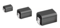
Chip inductors for SMD assembly

Printed coil with planar ferrite core

SMD transformer for Ethernet interfaces

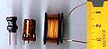
Rod core choke (left) and damping bead
Coils in different designs

Current-compensated choke on a ferrite core (D core)

Series choke for a fluorescent tube

Current-compensated choke on a ferrite core (ET core)


swell
- Understanding and using electronic components, FF Mazda, Telekosmos-Verlag, 1984, ( ISBN 3-440-05324-5 )
- uni-text, Electronics Volume 1: Components, 4th edition 1985, Bodo Morgenstern, Vieweg-Verlag, ( ISBN 3-528-33333-2 )
- Lexicon Electronics and Microelectronics, VDI-Verlag, 1990, ( ISBN 3-18-400896-7 )
- Trilogy of Inductors - Application Manual from Würth Elektronik ( ISBN 3-934350-30-5 )
- “Markt und Technik”, No. 7, February 2008, overview of manufacturers and suppliers of inductors
Individual evidence
- ↑ a b D. Sautter, H. Weinerth, Lexicon Electronics and Microelectronics, "Inductivity", page 365, VDI-Verlag 1990, ISBN 3-18-400896-7
- ^ Hering, Ekbert, Bressler, Klaus, Gutekunst, Jürgen; Electronics for engineers and scientists; 5th updated edition, Springer Verlag, ISBN 978-3-540-24309-0 , p. 127 ff
- ↑ Dr. Thomas Brander, A. Gerfer, B. Rall, H. Zenkner: Trilogy of inductive components Chapter: Fundamentals
- ↑ http://www.attempo.com/Daten/Kernstoffen.pdf , pp. 4, 5