
pantograph

Pantograph or pantograph (occasionally also pantagraf or pantagraph ) literally translated from Greek means all writer . The device, also known as a cranesbill , is a mechanical precision instrument for transferring drawings on the same, larger or smaller scale .
development
The mechanical pantograph was invented by Christoph Scheiner as early as 1603 . Today there are also optical pantographs.
application
Scaling drawings

In the past, pantographs were used in cartography and geodesy, for example, to reduce and enlarge maps and plans, and for a long time they were the only way to reliably transfer drawings with changing scales. Today, in the age of CAD and digital image processing , the pantograph no longer plays a major role in technology, but is still sometimes used as a painting toy for children and young people or for experimental purposes.
Mechanical pantograph: used for drawing patterns
Pantograph when scaling a map

Simple transformation aid ( reduction circle )


Scaling during milling work
Mechanical pantographs can also be found in copy milling machines , where they enable any desired scale of reduction through the infinitely variable adjustment of the joint angle or the pin receiver. In this application, enlargements are rarely used because the quality of the path guidance has technical limits and guidance errors are also scaled when enlarging. The guidance by means of a mechanical pantograph causes movement in all three spatial axes. In addition to the machining position, the machining depth or the lifting of the milling cutter from the tool can also be determined. The operator usually guides them manually. Such a device usually receives letter templates as a template, so that you can use it for B. can manufacture door signs. The large-area engravings made in metal or plastics are then often filled with color, unless the material is already built up in multiple layers of color.
In 1834, William Leavenworth designed the first wood type milling machine in the USA .
Watt mechanism
In the Watt mechanism , the Watt linkage and the Watt parallelogram are combined to convert a rotational movement (with the linkage) into a parallel movement and to translate this (with the parallelogram, which takes on the role of a pantograph).
functionality
General functionality

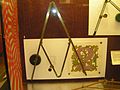
The pantograph consists of four strips (depending on the design) that are articulated to one another (see sketch, V1–3 and B are the joints). S indicates the point around which the pantograph is rotated. This is placed next to the template. In order to enlarge an original, this is traced with the pen B; Pin Z then generates the enlargement. To reduce the size, move the template with the Z pen; Pen B creates the reduction:

Notes: The route , to which point B also belongs, has been inserted for better illustration, it is not part of the construction. Due to the system, a copy factor of 1: 1 is only possible with specially designed leg constructions.

Mathematical explanation
The green lines indicate the bundle of rays, the blue lines the group of parallels. According to the theorems of rays:

So this means that at a ratio of , and S as a fixed point, the displacement of the point B by 1 LE ( L Ängen e nit) has a displacement of the point Z by three LE result. Thus, with the help of the pantograph, enlargements or reductions in scale can be created.


See also
- Spirograph
- Physionotrace
- Pantography
- Nuremberg scissors
- Puncturing device
- Scissor pantograph or pantograph pantograph
Web links
- Pantograph with dynamic geometry software (by H.-J. Elschenbroich and M. Rechmann) - only for Internet Explorer , created with DynaGeoX. Also enables effects with "crooked" pantographs
- Building instructions for a pantograph (English)
- Youtube: Age promotional clip for a marketed in the US pantograph (English)
- Storchenschnabel in The large art dictionary by PW Hartmann