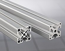
Construction profile
Construction profiles (also hollow chamber profiles or assembly profiles ) are elongated semi-finished products made of aluminum using the extrusion process .
There are different construction profile sizes and profile geometries as well as connecting elements and functional accessories and are used primarily in mechanical engineering and in automation technology for frame substructures, cladding, protective devices and functional applications.
On the one hand, construction profiles made of aluminum compete with profile steels ; on the other hand, depending on the task at hand, a mix of both materials can be the best solution, e.g. B. Frame construction made of aluminum profile with stiffening elements made of sheet steel.
Material and strength
The strength of the material aluminum is limited to a tensile strength of about 250 N / mm², since aluminum alloys in higher quality involve too great risks in the production in the extrusion process. Danger: tool breakage due to unfavorable flow properties. The density of aluminum is considerably lower than that of steel (aluminum ~ 2.7 g / cm³ | steel ~ 7.8 g / cm³). In comparison with steel (210,000 N / mm²), the modulus of elasticity of aluminum (70,000 N / mm²) is around Factor three lower. Aluminum is therefore less resistant to tension and compression. Since the formability of aluminum is much higher, this disadvantage is compensated for by optimized profile geometries. In the development and manufacture of structural profiles is to increase the moment of resistance as much material as possible placed at the edge of the geometry. Ready-to-install aluminum construction profiles are predominantly coated with an anodic oxidation layer ( anodizing ), which means that the corrosion protection is already included. Priming and painting can be omitted.
features
Construction profiles made of aluminum can be used very individually due to their lower weight and ideal malleability. The majority of the profiles have longitudinal grooves in which sliding blocks (old designation: sliding blocks) can be inserted or swiveled. These slot nuts have a threaded hole and can be moved within the slot. Thus, the slot nut can be referred to as a threaded hole that can be freely moved in the longitudinal direction, which is of great advantage for modern machine production.
In addition to slot nuts, other accessories can be inserted in the longitudinal grooves: sheet material such as acrylic glass, double wall sheets, polycarbonate panes, etc. The longitudinal grooves also serve to accommodate seals, adjustable feet and sliding elements. The cross-sectional area of the construction profiles often shows so-called screw channels, which are already pressed during manufacture. The tolerances of these channels are so fine that the respective screw with a metric thread can be screwed in directly without any preparatory work. If the screw-in depth is observed (2.5 × d (d = diameter of the screw)), the minimum tensile strength of the screw can be fully exploited. Example: The screw-in depth of a metric screw of size M6 is 2.5 × 6 mm = 15 mm.
Connection technology
In contrast to steel structures, in which welded connections are preferably used, the aluminum construction profiles are generally screwed or clamped. Each provider favors one or more connection technologies. The main difference is whether the profiles have to be machined at the ends or not.
- With machining of the profile ends
- The simplest form of connection is a screw connection, in which a through hole has to be made in a profile. The screw is screwed into the screw channel of the counter profile. There are also a number of special connectors, all of which require a more or less complex processing of the profile ends. Overall, the construction profile is weakened by the processing in the overall structure.
- Without machining the profile ends
- Machining-free connection technologies are offered. The end of the profile is not "damaged" in the case of the clamping bracket or flange strip connections - its structure is retained. Furthermore, there are no processing costs and the profiles can be used again for other tasks.
disadvantage
Compared to steel materials in particular, extrudable aluminum alloys have a tendency - due to their lower modulus of elasticity - to greater elastic deformation and must therefore have a geometry with an increased area moment of inertia . Structural steels such as B. S235 have slightly better strength properties (pronounced yield point Re) than the common aluminum materials such. B. AlMgSi0.5. The modulus of elasticity in steel (approx. 210,000 N / mm²) is approx. Three times as large as in aluminum materials (e.g .: Al Mn 1 F12 with 70,000 N / mm²), so that with the same geometry the elastic deformations are a third as high turn out big.
Specialty
The manufacturers have not yet agreed on any standard for the groove geometry and connection options. However, the external dimensions are identical for most providers. The so-called 40 series is the standard dimension within automation technology. These include profiles that have an outer dimension of 40 mm × 40 mm, 40 mm × 80 mm or 80 mm × 80 mm. These sizes can be found at almost every provider. Depending on the application, there are also versions in this series in lightweight construction or made of other materials such as stainless steel for use in the food sector or made of fiber composite materials. The profiles are typically named after the width of the groove, for example Profile 5 for construction profiles with a 5 mm wide groove. In addition to the common profile geometries from well-known manufacturers such as Item or Bosch Rexroth, there are a large number of smaller manufacturers who offer profiles and connection sets that are compatible with these profile geometries.
literature
- Application technology aluminum . VDI Springer, ISBN 3-540-62706-5
- Aluminum paperback . Aluminum Verlag, Düsseldorf, ISBN 3-87017-169-3
- Handbook for designers Sapa Gränges Group


