Programmable unijunction transistor
A programmable unijunction transistor (PUT, English ., Dt programmable unijunction transistor ) is a semiconductor - device and similar in structure to a thyristor . Its three connections are called the gate (G), anode (A) and cathode (K).
Structure and difference to the unijunction transistor
Like a thyristor, the PUT consists of four alternating p-, n-doped layers and thus contains three pn junctions (Fig. 1). It has an anode and a cathode connected to the first and last layers, and a “gate” connected to one of the inner layers.
The unijunction transistor (UJT), in contrast to a programmable unijunction transistor only one pn junction (Engl. Pn junction ) on. The established term “programmable unijunction transistor” is therefore misleading, as it is not a variation of the unijunction transistor (UJT), but a variation of the thyristor.
functionality
The PUT has an adjustable (“programmable”) switching threshold: If a voltage is applied to the anode and cathode, no current flows as long as the threshold voltage ( U S ~ U P ) is not reached. However, if the applied voltage exceeds the threshold voltage value , the AK path of the PUT becomes conductive. The threshold voltage can be modified (“programmed”) via a voltage U G applied to the gate . Fig. 1 shows the circuit symbol, the layer structure and the typical current-voltage curve of a PUT.
Areas of application
PUTs are not directly interchangeable with conventional UJTs, although PUTs perform similar functions. In the correct circuit design with two "programming" resistors for setting the system parameter η, they behave like conventional UJTs (Fig. 2). The 2N6027 is an example of such components.
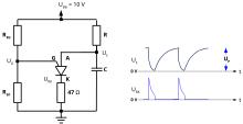
One advantage of the PUTs is that they can be used to build oscillators from a few discrete components (Fig. 3). Since the same purpose can also be achieved with inexpensive integrated circuits (e.g. timer NE555 ), PUTs are rarely used.
Mathematical description
The calculation of the electrical quantities from Fig. 2 is carried out using the equations below:
where is a system parameter.
literature
- Charles Platt , Philip Steffan (translator): Make: Electronics: Learning through discovery. O'Reilly Verlag, Cologne 2010, p. 83f.


