The following important information is missing from this article:
This article should be backed up with more sources (in most specialist books the real transformer is only mentioned briefly, if you can find relevant literature, please add). The model for high frequencies with winding capacities is also missing.
Help Wikipedia by
researching and
pasting it .
The real transformer is usually a linearized model of a transformer , which extends the ideal transformer to include stray fields, ohmic losses, hysteresis losses and possibly capacitive effects.
In a real transformer, not all of the magnetic flux produced by one of the coils also flows through the other coil. This phenomenon is called scattering . In many applications, scattering is undesirable, in others (e.g. resonant converters) it is an important component of the topology, since additional coils can be saved with specifically selected scattering factors.
Equivalent circuit diagram for low frequencies

A real transformer with windings and magnetic fluxes
Electric and magnetic circuit
The adjacent figure is clearly shown in the following circuit diagram:

This circuit diagram includes two electrical circuits and one magnetic. The coil windings N 1 and N 2 act as a coupling between the electrical and magnetic circuit.
The leakage fluxes are shown in the equivalent circuit diagram as magnetic resistances R m, σ1 and R m, σ2 . A current I 1 creates a flow in the magnetic circuit at N 1 , so that . The magnetic resistance R m, h that the main flux Φ h experiences is divided here for reasons of symmetry. In a very good approximation, R m, h is the magnetic resistance of the iron yoke. The resistors R 1 and R 2 represent the resistance of the coil windings.


Symmetrical equivalent circuit
In the next step, the magnetic circuit is transformed into electrical circuits:

The coil windings N 1 and N 2 merge to form an ideal transformer with a transformation ratio . In the transformation by the gyratorischen couplings coils connected in parallel, magnetic resistances connected in series inductances are:
,
,
and
.


Note : Often there is also talk of primary and secondary main inductance, which however mean the transformation of both coil halves on one side and must therefore never be drawn in the same equivalent circuit diagram! This often leads to confusion.
T equivalent circuit diagram
Every linear two-port can be represented as a T equivalent circuit diagram. The steps shown above give the individual components of this circuit diagram a direct, real reference. The ideal transformer is extracted from the circuit diagram:
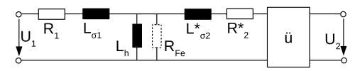
A new addition here is the resistance R Fe , which symbolizes the hysteresis losses in the core that have not been taken into account so far .
During the transformation through the transformer coupling [ü], parallel / series connections are retained and the following applies: and The two inductances L h, 1 and L h, 2 merge to form the (primary) main inductance .


The T equivalent circuit shown above expands the ideal transformer [ü] by the real effects. The transmission behavior of the real transformer results from the concatenation of the ideal and the real transformer in chain parameters (current direction I 2 away from the two-port!) As follows:
-
 wherein with

The T equivalent circuit is usually used for circuit analysis.
Parameters
Self inductance
The self-inductance of a transformer is calculated as follows:


where the magnetic conductance and Φ 11 is the portion of the magnetic flux that is caused by the current I 1 ( superposition ) and runs through the coil windings N 1 (Φ 22 equivalent).

The self-inductances can be measured at the transformer terminals when the other side of the transformer is open (idle). Note: In the magnetic circuit from the first circuit diagram, N 2 acts like a short circuit when the terminals in the electrical circuit are open ( gyratory coupling ).
Mutual inductance
The mutual inductances are defined as:


As shown above, the two mutual inductances are the same in the case of linear materials (as previously assumed). Thus the size is referred to as mutual inductance .


Coupling factor
The so-called flux coupling factors are defined as follows:


 is the portion of the magnetic flux through which is caused by electricity . Accordingly, the following applies: .


You can also write:

- →

- →

- →

with a common coupling factor
where is. For perfect coupling is .


Spreading factor
Equivalent to the coupling factor, scattering factors can be defined as follows:


The factor is called the Blondel coefficient or simply the scatter factor.

In the case of a symmetrical, capacitance-free transformer (
), the Blondel coefficient can e.g. B. easily determine with an LCR meter by inductance measurement:


where L open = L 1 is the measurable inductance at the input with an open output and L short is the measurable short-circuit inductance at the input with a short-circuit of the output (input and output are interchangeable here).
Individual evidence
-
↑ cf. Dieter Zastrow: Electrical engineering: a basic textbook . 17th edition. Springer-Verlag, 2010, ISBN 978-3-8348-0562-1 , section: Realer Transformator , p. 330 .
-
↑ Manfred Albach: Inductivities in power electronics . Springer Fachmedien Wiesbaden, Wiesbaden 2017, ISBN 978-3-658-15080-8 , doi : 10.1007 / 978-3-658-15081-5 .
-
↑ Practical Basics of Electrical Engineering Experiment: Magnetic Circle. HTW Dresden, August 2011, accessed on September 5, 2015, p. 9.
-
↑ Wolfgang Demtröder: Experimentalphysik 2: Electricity and optics . 5th edition. Springer, Berlin / Heidelberg 2009, ISBN 978-3-540-68219-6 , pp. 150-154 .
-
↑ Ing: GdE: Models of the transformer - Wikibooks, collection of free textbooks, non-fiction and specialist books. In: de.wikibooks.org. Retrieved November 4, 2016 .


