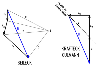
Rope corner method
The rope corner method is a graphic method in statics to determine the resulting force (resultant), from which one can then, e.g. B. with the help of the Culmann method , the support reactions can be determined.
If several forces lie in one plane that do not act at a common point, the position of the resultant can be determined with this method: a figure, the so-called Poleck , is drawn, in which the individual forces are added as force arrows to determine the size and direction of the Determine the resultant and then be connected by pole rays with a point, the pole . The pole rays are then transferred to the site plan as so-called rope rays , where they form the rope corner and enable the line of action of the resultant to be determined. The term Seileck is also used in a broader sense for the Poleck.
Procedure
In the example there is a beam on two supports A and B, on which the forces F 1 , F 2 and F 3 act according to the sketch. First the forces are drawn to scale as force arrows according to the sketch below and added geometrically. The forces F 1 , F 2 and F 3 are shown continuously lined up on their lines of action so that the arrowhead of the next force follows the arrowhead. If you connect the beginning of the arrow of force F 1 with the arrowhead of force F 3 , you get the resulting force R according to magnitude and direction. Then you draw so-called pole rays (connecting lines) from any point S chosen to the ends of the individual force arrows and number them consecutively. The triangles created in this way represent force corners, whose pole rays intersect with the associated forces at points I, II, III and P of the sketch above.
With the construction of the rope corner according to the sketch above, the position of the resulting force R results. You start with the line of action of the force F 1 and bring this with the associated pole rays from the force corner, i.e. 0 and 1, to the intersection at point I. The same applies to the forces F 2 and F 3 . At the intersection P of the pole rays 0 and 3 lies the line of action of the resulting force R, the point of application of which on the beam is determined by moving the force arrow. The same lines of action of the forces and of the pole rays in the various sketches must of course always be parallel.
The support reactions are determined here with the help of the Culmann method :
The line of action of the resultant R is brought to the intersection with a line of action of support (here B). This point of intersection is connected with the point of intersection of the other two support lines of action (here A V and A H ). This connecting line is the so-called Culmann line .
A force corner is now formed from the resultant R with the lines of action from the support reactions A (A V and A H ) and B. This force corner can also be represented in the rope corner; a separate force corner has been drawn here for better clarity.
See also
proof
- ^ [1] , in the Baulexicon from Beuth Verlag
- ↑ [2] , in the building dictionary from Beuth Verlag

