
YUV color model

The YUV color model is used in analog color television according to the PAL and NTSC standards.
It uses two components to represent the color information:
- the luminance ( luma , luminous intensity per area, i.e. luminance ) Y and
- the chrominance (color component, chroma ), which from the two sub-components U and V is.
A color model is often confused with a color space, but there is just as little a YUV color space as a YPbPr or YCbCr color space (see below).
boundary conditions
The ink transfer was first developed in analog TV, as black and white were established -Fernsehgeräte which used only the luminance signal Y, already on the market. As a rule, the color television should disturb the black and white receivers as little as possible. In order to achieve this downward compatibility , technical ways were sought to transmit the color information in addition to the black and white signal without increasing the available transmission bandwidth . For this purpose, the color signals U and V were quadrature-modulated with different amplitudes on the color subcarrier , which results in distortion factors between YUV and YPbPr (see below).
principle

Like the color triangle from which it was derived, the YUV color model is based on a model with linear addition of the color stimuli . These models can be converted into one another with the help of a matrix .
To calculate the luma signal Y, the underlying RGB data are first offset against the gamma value of the output device; an R'G'B 'signal is obtained. The three individual components are added with different weightings to form the brightness information that works as a BAS signal even with old black and white television sets.
The weighting of the components is necessary because some aspects of the color vision of the human eye must be taken into account. For example, green is perceived as lighter than red, which in turn is perceived as lighter than blue. This different weighting is taken into account in the following ( by definition exact) conversion formula:

The chrominance signals (also color difference signals ) U and V contain the color information. They arise from the difference between blue component B and luminance Y or between red component and luminance and a further reduction ; these formulas are also exact by definition :

The individual color components of the basic colors can later be calculated from the three components Y, U and V generated (the formulas for G are approximate):

or.

Furthermore, the structure of the retina of the human eye means that the brightness information is perceived in a higher resolution than the color. Many formats based on the YUV color model use this to reduce the spatial resolution of the chrominance in order to save bandwidth during transmission.
The image resolution is standardized by the Common Intermediate Format (CIF).
- UV areas in a value range of [-1.1]

Y value 0
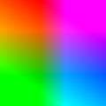
Y value 0.5

Y value 1


Comparison with other color transmission systems
YPbPr and YCbCr
YUV (devices, cables, coding, color model) is often incorrectly referred to when actually referring to the YPbPr model (for analog connections or cables) or the YCbCr model (in the digital sector); both are defined in the CCIR 601 and IEC 601 standards.
The YUV color model differs from the related YPbPr and YCbCr models in the scaling factors (amplification or attenuation factors) relating to the color signals. I.e. the UV color diagram shown at the top is distorted in the U or V axis by certain fixed factors in order to obtain the PbPr color diagram:

The distribution of the colors in the plane is retained, the brightness signal Y is identical in all these models.
The reason is that the YPbPr model as well as the YCbCr model spans a symmetrical surface in the color plane and thus the two factors Pb and Pr (or Cb and Cr) are evenly scaled, which enables easier signal processing .
In contrast, the YUV color components U and V are distorted to different degrees in the color plane: U is used at a lower level than V. This makes signal processing more difficult, but with quadrature modulation on the color subcarrier it results in the lowest possible interference in the brightness signal.
YIQ
The YIQ color model previously used in the NTSC color television standard, like YUV, has different intensification factors for the color channels (referred to here as I and Q), since the already established black and white television sets should be disturbed as little as possible. In addition, with YIQ the color plane is rotated by 33 ° clockwise. As a result, the color components I and Q are assigned different color values than is the case with UV, PbPr and CbCr.
In terms of circuitry, this rotation is much more difficult to implement when switching from YIQ to YPbPr and to YCbCr, which is why the YUV color model has also been used for analog NTSC since the 1970s.
See also
literature
- Charles Poynton: Digital Video and HDTV Algorithms and Interfaces . Morgan Kaufmann Publishers, San Francisco 2003, ISBN 1-55860-792-7 (English).
Web links
Individual evidence
- ↑ a b International Telecommunication Union : ITU-R BT.1700 Characteristics of composite video signals for conventional analogue television systems. (zip / pdf) 1700-e.pdf: PAL signal format and specification. July 6, 2007, p. 4 , accessed April 15, 2019 (English).
