
Centrifugal extractor

A centrifugal extractor is used for the continuous extraction of valuable substances (metals, active ingredients, aromas, vitamins, etc.) from one liquid phase into another liquid phase with the help of centrifugal force . Two immiscible liquids (carrier / solvent) of different densities are intensively mixed in a mixing space between the housing wall and the outer rotor wall. The intensive mixing creates small droplets with large surfaces that enable optimal mass transfer from the carrier phase to the solvent phase. A centrifugal extractor then uses centrifugal force to separate the finely dispersed droplets.
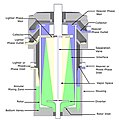
Single stage centrifugal extractor
The sectional drawing shows a cross section through a single-stage centrifugal extractor. Either pre-mixed or two unmixed liquids (blue / yellow) are fed to the mixing area (green) of the centrifuge via the two inlets. The phases are strongly mixed in the mixing area between the rotor and the housing wall. Small droplets are created and thus a large surface area in order to optimize the exchange of substances for washing and extraction processes. The intensity of the mixing can be selected via the rotor speed. The dwell time in the rotor is between 30 seconds and two minutes per stage. In the rotating rotor , the two liquids of different densities are separated by centrifugal forces and drained off via the respective discharge (heavy or light phase).
Separation DF (direct feed)
With "direct feed", the mixed liquids (green) are fed through the base plate directly into the rotor, thus minimizing the shear forces on the product. The two phases are continuously separated into a heavy phase (blue) and a light phase (yellow).
Mix & Sep
With “mix & sep”, two immiscible liquids (blue and yellow) of different densities are brought into contact outside the rotor. The shear forces generated in the narrow gap between the rotating rotor and the static housing wall form very small droplets with a large surface for the ideal mass transfer from one phase to the other. Both phases are then separated from each other in the rotor.
Multi-stage centrifugal extractor

The phase to be extracted (heavy phase on the basic circuit diagram), which initially contains one or more solvates, and the solvent (light phase on the circuit diagram), which must not be miscible with the phase to be extracted and must have a different density, flow in countercurrent into the extractor rotor, in which stacked mechanical parts form a certain number of stages. The successive mixing and separating processes in each stage enable the solvates to dissolve in the solvent.
Each level consists of the following parts:
- A mixing chamber in which the two phases are mixed and the transfer of the solvates to be extracted takes place. A fixed disk enables the two phases to be mixed and a fine emulsion to be formed . It works like a pump that draws in the two phases from the preliminary stages.
- A decanting chamber in which the two previously mixed liquids are separated by centrifugal force. Two weirs stabilize the separation zone regardless of the amount of liquid. The position of the phase interface depends on the weir diameter of the heavy phase. The weir is exchangeable and is adapted to the density ratio of the two phases.
Multi-stage processes
Multi-stage processes are required for applications with several theoretical stages. Each single-stage centrifugal extractor represents a theoretical stage. Cross-flow and counter-flow processes are represented in this way.
Sectional drawing

Separation DF

mix & sep

Cross and countercurrent extraction

Battery of two centrifugal extractors for countercurrent extraction in two stages


Web links
- [1] At: you tube video explanation
- Centrifugal extractor washes, extracts and separates in one step. At: process.vogel.de.
- Extraction. New centrifugal extractor for liquid media. At: process.vogel.de.
- Multistage centrifugal extractor. Patent.