
Section (representation)
A sectional drawing, sectional representation or also briefly a section is a form of representation in drawings. It is also known (especially in the construction industry ) as a crack drawing or crack for short , from which the terms floor plan and elevation (the view) are derived. Depending on the cutting plane , the drawings are referred to as a longitudinal section or a cross-section (less often the floor plan is also referred to as a floor plan section).

A sectional drawing is used to show hidden internal contours , materials and structures of a body . If necessary, different cuts must be made through a body in order to be able to represent all relevant details in several cut surfaces.
Areas of application
Sectional drawings and representations are used in many areas. In technical drawing for the representation of structural elements and components in mechanical engineering or in the building industry (structural engineering, civil engineering); in the representation of buildings in architecture ; in the clear presentation of devices and machines for laypeople; in the science fiction scene, where fans or authors portray fictional spaceships and space stations ; in biology when depicting the structure of flora and fauna ; in the representation of the layers in the ground in geology and archeology ; in medicine for tomographic imaging of the human body and so on.
presentation

In classic sectional drawings, the cutting edges are shown thicker than the contours of the elements that you see in the view . The cut surfaces are often flat or filled with hatching . Depending on the area of application, there are different rules for sectional drawings.
In mechanical engineering, for example, special rules apply to the representation of cut threads , bores and fits as well as to their dimensions .
Conventions also apply in construction. Regulations apply to the presentation of the construction drawings in the official building application procedure ( building template ordinance )
If the cutting plane runs through several bodies, the cutting surfaces are to be represented by hatching in different directions. Different types of hatching are used to mark different materials (metal, concrete, masonry, wood, textiles, plastic, etc.) (e.g. line, cross-line, dashed line, point hatching, etc. in different line widths and spacings as well as grids and areas in different shades of gray or color).
Rotational bodies cut lengthways (parallel to the axis) (e.g. rotating bodies, plant seeds) are shown as uncut bodies (in the view) as agreed; its axis as a dotted line. Edges in front of the cutting plane or hidden contours behind it can be displayed, then with dashed lines. Most of the time, the parts that are visible next to the cut part and that lie behind the cutting line are also shown (with very thin lines). The viewing areas lying there can be displayed naturalistically - also photo-realistically ( CAD , animation ).
On the other hand, such a view drawing can also be displayed with a neutral cut surface (as continuous, uniform hatching, in a flat filling or blackened “Schwarzplan”, “blackened section”). Different materials cannot be seen in the representation.
In addition to the classic, two-dimensional sectional drawings, there are also perspective drawings, which are often created from models generated in the computer. They are often easier to understand for laypeople . Occasionally, sectional drawings are blown up by showing individual areas offset for a better overview and thus not obscuring each other. One then speaks of exploded views .
Examples

Perspective sectional drawing

Three-dimensional sectional drawing through a mitochondrion in biology
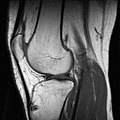
Sagittal cross-section of a knee joint by MRI
_Vicenza_ricostruzione_spaccato_prospettico.jpg)


See also
literature
- Hans Hoischen , Wilfried Hesser: Technical drawing . 30th edition. Cornelsen Verlag, Berlin 2005, ISBN 3-589-24110-1 .