
Technical drawing

.jpeg)


Technical drawing is the production of technical drawings used in mechanical engineering and construction by engineers (especially designers ), architects , technical draftsmen and construction draftsmen . The drawings used in construction and architecture are more specifically called construction drawings .
The standardized and regular and complete technical drawings are created i. d. Usually only at the end of the construction process and are made by technical or construction draftsmen according to the often only sketchy drafts of the engineers and architects that mostly only define the function of the products.
Classic and modern
The history of manual, technical drawing
Many of the geometric foundations of technical drawing, which were discovered and researched before the birth of Christ, go back to famous mathematicians such as Pythagoras of Samos or Euclid of Alexandria .
From the Middle Ages to the 18th century
The beginnings of the architectural, technical drawing were laid in or before the Middle Ages . B. the St. Gallen monastery plan or the drawings by Villard de Honnecourt , who u. a. also drew a perpetual motion machine , prove.
An early representation of a gear can be seen in the drawing of a pumping station by Al-Jazari , who also drew an imposing machine based on the principle of a pendulum balance with two weighing pans and functioning with the help of water power. Further medieval, technical sketches relating to the construction of machines have come down to us from Guido da Vigevano , among others , who drew a crank car and a submarine .
An important prerequisite for technical drawings was the invention of the central perspective , which is attributed to Filippo Brunelleschi around 1420. Albrecht Dürer promoted the spread of this form of representation. In the 15th century AD Taccola drew various technical devices such as B. a paddle wheel boat or a horse-powered göpel . Technical drawing was further refined by Leonardo da Vinci , among others . Not only did he depict machines and machine parts realistically, but he also added elements to his drawings to aid understanding.
A very great developer in the field of technical drawing was Georgius Agricola , who first explained mining and ore processing in his book on metal science "De re metallica libri XII" (published 1555) through technical drawings.
A next step can be demonstrated by Leonhard Christoph Sturm's "Complete Mühlenbaukunst" (1718), which contains drawings for the first time that depict the machines to scale. The materials used are also taken into account.
The French inventor and aviation pioneer Jacques de Vaucanson constructed a hook chain and various automatons in France in the 18th century . He drew his mechanical duck (see full section below) in 1738.
Technical drawing in the 19th century
Further evidence for the development of technical drawing can be found in early patent specifications from the 19th century. However, since the first patents were granted in England in the 13th century, it is quite possible that much older technical drawings can also be found in patents. The discipline of technical drawing has evolved over centuries into a modern technology. In traditional technical drawing on the drawing board , various drawing tools such as drawing tools , compasses , pencils ( mechanical pencils ), erasers , fiberglass erasers , writing stencils and curve rulers or even ink pens or funnel nibs are used today .
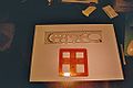
The following illustrations of devices for technical drawing and the hatching types customary at the time come from the Encyclopedic Dictionary Brockhaus and Efron , which appeared in Russian between 1890 and 1906.
- Historical drawing tools and hatching
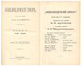
Title page of the encyclopedia

Drawing instruments 1

Drawing instruments 2

Material hatches


Technical drawing in the 20th century
Until around 1910 (for some applications until around 1965), drawings were made almost exclusively with pencil and ink on tracing paper. This was stretched with drawing pins or masking tape on a drawing board (drawing board) or the inclined board of a drawing machine . With the introduction of more modern tracing techniques such as the blueprint process , the tracing paper has been replaced more and more by transparent drawing foils .
- Drawing tools
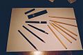
Crayons
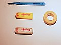
Erasers, adhesive strips

Drawing machine
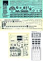
Various rub-off foils for applying symbols, signatures, etc. a.

Funnel nibs are the forerunners of the India ink pen


Drawing triangles ( geometry triangles ) and rulers were initially used as aids for precise drawing, and later almost exclusively drawing machines . For geometric constructions and circular display were circle or circle template for radii special radii template called and for drawing curves Burmester templates used.
Special geodetic drawing instruments for mapping the measurement points of topographical and architectural surveys , kleinmaßstäbiger plans and inventories were the transporter (combined route and protractor), the prism scale and dividers for running - and clamping dimensions , a pair Abschiebedreiecke , and from the 20th century Mapping machines like the coordinatograph .
- Rulers and templates

Geometry triangles
Rulers and right angles
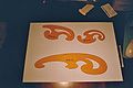
Curve rulers ("Burmester sentence")


Classic technical drawing has lost a lot of its importance since the mid-1990s. Companies such as Rotring were once geared towards this special requirement and are now only part of a large conglomerate that supplies a changed market with office supplies.
... the present of computer-aided, technical drawing
In the mid-1960s, the company switched to computers , CAD programs and plotters . First of all, programs for 2D representation were developed, which initially only allowed the representation of different views. Initially, only the medium of paper or ink was replaced by digital storage.
The construction method of digital drawings was initially very similar to the method used on the drawing board, but drawings could be changed and reproduced much faster. The reuse of parts of the drawings was also made much easier by copying methods such as copy & paste and even entire drawings could now be easily reproduced on the computer. Since then, modern, technical drawing has mainly taken place in front of computer monitors .
A new, changed type of technical drawing was then gradually made possible by the programs for 3D representation that emerged from the mid-1980s . No drawing in the classic sense is created, but a 3D model of the object is modeled. Today's programs can completely derive views at any cutting angle and any projection from these 3D models and convert them into digital technical drawings. In addition to this new, consistently used method, the manual method is still taught as a basis at some secondary schools and a few technical colleges.

Technical drawing 1980 (CAD)

CAD exploded view and sectional view

AutoCAD 3D model (compilation)

3D rendered drawing of a vice


Technical drawing using CAD (Computer Aided Design)
Due to the enormous technical change since the mid-1990s, hardware and software manufacturers have largely displaced the classic need for technical drawing and established CAD systems that soon established a connection to computer-aided manufacturing so that digital technical drawings can be implemented directly on the machine tool could.
At the beginning of the 21st century, companies such as Graphisoft (with ArchiCAD ), Autodesk (AutoCAD), Parametric Technology Corporation (Pro / ENGINEER, Creo) and SolidWorks dominated part of the market. In the automotive industry, u. a. CATIA from Dassault Systems is one of the standard tools used by engineers. The computer animation on the left is animated screenshots from a CAD program that covers practically all stages of technical drawing, from drawing a 2D view and dimensioning it to 3D modeling the body including rounding the edges with radii and rendering .
The arrows labeled XC, YC and ZC in the model symbolize the two-dimensional, but generally three-dimensional coordinate system used for the representation of the views , which serves as a reference for each model. The origin of this coordinate system can be defined by the designer as in this animation within the body, but can also be placed at any other point such as a corner or in the middle of an edge or even at a reference point completely outside the actual object.
The blue lines indicate one of the three levels on which the coordinate system is located, whereby the different colors for lines, surfaces, dimensions, etc. can also be defined by the CAD draftsman.
The AutoCAD drawings on the right show how realistic 3D representations can be using modeling and rendering techniques . The group drawing (above) shows various components after assembly and differs from a so-called assembly drawing in that the latter is used to explain assembly processes, while an overall drawing depicts very complex systems such as machines, devices or entire systems in their finished state. These and similar terms used in technical drawing are regulated by DIN 199 , which defines the terminology in Part 1 for drawings and Part 2 for parts lists.
The model of the vice at the top right shows how the boundaries between drawn objects and reality are so blurred through modern CAD technology that untrained eyes can hardly distinguish between reality and simulation .
Technical drawing with the help of various CAD programs corresponds to the state of the art around the turn of the millennium , although the requirements for the hardware of the computers that are used for drawing have changed over the past few years. While special workstations with so-called RISC processors were often used in the 1980s and 1990s , CAD applications for technical drawing were increasingly running on personal computers with correspondingly powerful graphics cards .

Components of the assembly
|
The possibilities of modern technical drawing by means of a CAD system, as it is used today in machine , plant or apparatus construction , illustrate these different sectional perspectives of a spherical roller bearing .
Components and bearings are separated from one another in the views and sections using different colors instead of hatching. |
| No. | Component |
|---|---|
| 1 | Axis or shaft |
| 2 | Groove nut (DIN 981), green |
| 3 | Locking plate (DIN 5406), blue |
| 4th | Rolling bearings (here: spherical roller bearings) |
| 5 | Adapter sleeve (DIN 5415), red |


Digitization of existing drawings
Before creating a new CAD drawing, it is often preferred today to digitize existing drawings using a scanner with subsequent vectorization of the drawing data by the computer, as this data acquisition process further minimizes the manual work involved in technical drawing and thus brings significant time and cost savings.
After a subsequent drawing check and correction of any errors, the digitized drawing can then be further detailed.
Rules and standards in technical drawing
Standards such as DIN standards or ISO play an essential role in technical drawing .
Line styles
Different types of lines have different meanings in technical drawing. ISO 128 defines their exact designation and use.
- A wide solid line generally defines visible body edges and outlines, certain parts of a thread, etc.
- Narrow solid lines are mainly used for light edges, dimension and auxiliary lines, hatching , the root circle of a toothing, etc.
- Dashed lines indicate invisible, hidden body edges and outlines.
- Freehand lines are used, among other things, for break lines in the abbreviated representation of long components, such as when drawing interrupted shafts or steel girders . Another use of the freehand lines can be found in cuts, which are described in the following text. Zigzag lines can be used like freehand lines.
- Dash-dotted lines are used as center lines ( axes of symmetry and rotation axes ), pitch circles of gears, bolt-hole circles, etc., while dash-two-dotted lines are used for outlines of adjacent components, cutting planes and the like.
| Line style | Line width in mm | ||||
|---|---|---|---|---|---|
| Wide solid line, wide dashed line, wide dashed line | 0.25 | 0.35 | 0.5 | 0.7 | 1 |
| Narrow solid line, zigzag or freehand line, narrow dashed line, narrow dash-dot and dash-two-dot line | 0.13 | 0.18 | 0.25 | 0.35 | 0.5 |
The line widths to be used are based on the table above, whereby a third line width between wide and narrow lines can be used for labeling according to DIN 6776-1. The following table then applies, whereby the average line width is used for font, graphic symbols and invisible edges.
| Line group | Preferred for sheet format | Line width in mm | ||
|---|---|---|---|---|
| 0.5 | A2 and smaller | 0.25 | 0.35 | 0.5 |
| 0.7 | A1 and A0 | 0.35 | 0.5 | 0.7 |
Accordingly, the various manufacturers of drawing supplies offer ink pens in different line widths.
- Line styles

Freehand line

Zigzag line

Wide solid line

Narrow solid line

Broad dashed line

Narrow dashed line

Broad dash-dotted line

Narrow dashed line

Dash-two-dot line
Views

A basic distinction is made in technical drawing between the following views:
- Front view (1st main view)
- Right side view
- Side view from the left (2nd main view)
- Top view (3rd main view)
- Rear view
- bottom view
The main views mentioned relate to the European representation variant, whereby the object to be represented is usually drawn in these three views and secondary views are only used if the geometry to be represented is so complex that it cannot be completely described using the main views.
In the European version of the normal projection , the side view is from the left to the right next to the front view, in the American version on the left side of the front view.
According to DIN 6, a symbol for the projection plane is therefore integrated in the drawing header to distinguish it.
- The views and their projection

Body to be represented in the projection cuboid

2 main views and side view from the right
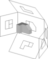
Unfolding the cuboid

The six views in European representation


Sectional views
Sectional representations are used quite generally to represent elements and contours that are normally hidden inside the component to be represented and are to be visibly represented for purposes of production , the associated documentation or explanation of function.
Section types, section limits and hatching


In the case of detailed and assembly drawings, the schematic representation of sections in partial section, half section or full section is widespread, although some special rules must be observed for their professional representation in technical drawings.
For example, freehand lines are to be used to highlight cutting boundaries for cutouts and the cutting path is to be marked in an uncut view with arrows that define the direction of view of the cut. When changing the cutting path within a drawing, a kinking cutting path must be marked accordingly in a view.
Hatching lines should generally be made at an angle of 45 ° or 135 °, the distance between the hatching lines must be adapted to the size and scale of the drawing, although this rule (as the sections shown) clearly leaves room for interpretations by the respective draftsman.
Opposing hatchings with different line spacings are used in technical drawing not only to differentiate between different components, but also to represent different materials. Details on this as well as on the colors that can be used are regulated by ISO 128-50 (previously DIN 201 ). In the case of large objects, complete hatching can be dispensed with and instead only the edge of the object along the body edges are hatched.
The representation of invisible edges in sectional representations should largely be dispensed with in favor of the overview.
Full cut
A full section is understood to be a view that only shows the sectional representation. This section runs, for example, along the axis of a body or perpendicular to it. Another possibility is the cutting course along a significant inner plane of the object to be displayed. In the full section, only the half behind the section plane or the remaining part of the body behind this plane is shown.
- Various sectional views

Mechanical duck (1738)
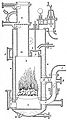
Steam boiler (1876)
Support (1904)
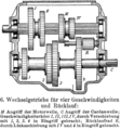
Gear cut (1911)
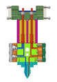
Dosing head (2006)

Dichroscope (2006)

Splined shaft (2007)

Belt drives (2007)


Half cut
A half section is understood to be a sectional representation in which, in contrast to the full section, not just one, but two perpendicular cutting planes run in the body to be represented. As a result, a quarter of the body is shown separated from the object in question. The half-cut is mainly used for bodies of revolution .
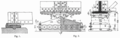
While the horizontal half-section (Fig. 15 and Fig. 16) from 1904 shows the views below and the respective section above, according to the current rules for horizontal half-sections, the reverse arrangement (top view, section below) is common. For vertical half-sections, the view on the left and section on the right apply today.
Partial cut and breakout
A partial section is understood to be a sectional view in which a certain section (for example of a larger object) is shown as a separate detail in the section, whereby the hatching can remain open to the outside in a partial section, while a breakout (an apparently broken continuation) through a Freehand line is limited (to the non-intersected adjacent area).
Profile section
If a profile (e.g. steel profile ) is shown in section, this section can be drawn within a view of the profile with narrow solid lines or next to a view with wide solid lines.
Angled cutting line
Furthermore, sections in different directions can be displayed within a drawing. In the full section with dimensions shown above, for example, a representation of two half-sections would be possible, whereby the second section axis could then be selected rotated by 90 ° and the course B-B through a corresponding right angle in the center of the circular view and one rotated by 90 ° B would be marked. The sectional view would then show one section in the upper half and the other section in the lower half.
Dimensioning and labeling


The geometry shown is quantified by the dimensions . Standards also play an important role in the dimensioning and labeling of technical drawings. The basic elements of the dimensioning (see illustration on the right) are:
- Dimension arrow on the left
- Dimension line
- Measure
- Witness line
- Dimension arrow on the right
Instead of dimension arrows, points or slashes can be used to limit dimension lines, for example if there is insufficient space or to simplify sketches . DIN 406 defines the general principles for dimension entries in technical drawings and other technical documents. The so-called general tolerances are defined globally in the drawing header of the technical drawing for the entire component shown in the drawing.
ISO 2768-1 defines the rules for general tolerances for lengths and angles and ISO 2768-2 the corresponding general tolerances for shape and position .
Furthermore, the rules of the EN ISO 1302 standard for entering surface information and several standards for the dimensioning of fits must be observed.
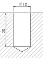
- Bore and thread in technical drawing


Lettering field according to EN ISO 7200
Further information on dimensioning and labeling, including the entries in and above the title block , can be found in the relevant standard and in the article Technical drawing .
Special norms
A complete presentation of all valid standards for technical drawing is not intended at this point. Rather, the most important standards that are used in technical drawing are to be listed here. For further details, please refer to specific literature on the subject. Specific standards for architectural drawings are listed in the Standards section of the relevant article.
DIN standards
| standard | Area | content | description |
|---|---|---|---|
| DIN 5 | presentation | Isometric and dimetric representation | Use in technical drawing (replaced by ISO 5456-3 ) |
| DIN 6 | presentation | Views and sections | Representation in technical drawing (replaced by ISO 128 ) |
| DIN 15 | presentation | Line styles | Use of solid lines, freehand and zigzag lines, dash-dotted lines (axis), dash-two-dot lines, etc. in technical drawing (replaced by ISO 128-20 or ISO 128-24) |
| DIN 30 | presentation | Simplified representations | Use in technical drawing |
| DIN 199 | Terms | Technical product documentation | Terms and definitions for CAD models, technical drawings and parts lists for technical product documentation in the field of mechanical technology. |
| DIN 201 | presentation | Hatching and colors | Use in technical drawing (replaced by ISO 128-50) |
| DIN 406 | labeling | Dimension entries, tolerance symbols, etc. | Use in technical drawing |
| DIN 919 | Wood processing | Technical drawings, woodworking | Use in technical drawing |
| DIN 1356 | Construction drawing | Representation of lines and hatching in construction drawings | Use in technical drawing |
| DIN 2429 | Pipeline construction | Pipelines icons | To be used for technical drawing of pipelines |
| DIN 2481 | Thermal power plants | Thermal power plant icons | To be used for technical drawing of circuit diagrams |
| DIN 6771 | Paper sizes | Drawing sheet formats | Classification and labeling for technical drawing ((Part 6 corresponds to the previous DIN 823 ), August 1999 replaced by EN ISO 5457 , paper format , Part 1 replaced by EN ISO 7200 ) |
| DIN 6775 | Drawing devices |
|
Test standard for ink pens, drawing and writing templates (replaced by ISO 9175 ) |
| DIN 6776-1 | labeling | ISO standard font | Use in technical drawing (replaced by EN ISO 3098 ) |
| DIN 7154 | Fits | System of fit unit bore | Use in technical drawing |
| DIN 7155 | Fits | Fit system unit shaft | Use in technical drawing |
| DIN 7157 | Fits | Selection of fits in the unit bore system | Use in technical drawing |
| DIN 7182 | Terms | Basic concepts of tolerances and fits | Use in technical drawing (replaced by ISO 286 –1) |
| DIN 24300 | Fluid technology | Circuit symbols for oil hydraulics and pneumatics | Technical drawing of hydraulic and pneumatic circuit diagrams |
| DIN 40900 | Electrical engineering | Electrical symbols | Technical drawing of electrical circuit diagrams (replaced by DIN EN 60617 ) |
ISO standards
| standard | Area | content | description |
|---|---|---|---|
| ISO 128 | presentation | Technical drawings | General principles of presentation |
| ISO 286 | Fits | Fits | ISO tolerance system for fits |
| ISO 1219 | Fluid technology | Fluid power circuit diagrams | Requirements for creation |
| ISO 2162 | presentation | feathers | Representation in technical drawing |
| ISO 2768-1 | presentation | General tolerances for lengths and angles | Use in technical drawing |
| ISO 2768-2 | labeling | General tolerances for shape and position | Use in technical drawing |
| ISO 5455 | labeling | Standards | Use in technical drawing |
| ISO 6410 | presentation | thread | Representation in technical drawing |
| ISO 9175 -1 | Drawing devices |
|
Test standard for ink pens, drawing and writing templates |
EN ISO standards
| standard | Area | content | description |
|---|---|---|---|
| EN ISO 1302 | labeling | Surface textures | Information in technical drawing |
| EN ISO 3098 | labeling | Technical product documentation, fonts | Use in technical drawing (replaces DIN 6776-1) |
| EN ISO 5457 | Paper sizes | Sheet sizes | Use in technical drawing (replaces DIN 6771 -6) |
| EN ISO 7200 | Title block | Data fields in title blocks and document master data | Use in technical drawing (replaces DIN 6771-1) |
Further rules
Adjustments , keyways and grooves, screws, springs and other connecting elements whose dimensions , shape and position tolerances , dimensions and tolerance records, roughness of surface, line thicknesses, sheet sizes , text fields and other information in the title block , hydraulic, pneumatic, electric and electronic switching characters and Circuit diagrams, parts lists and many other rules of technical drawing are explained in detail in the literature.
Further information on the use of circuit symbols when creating circuit diagrams in technical drawing can be found here in this article.
Rules through the ages


While the above-mentioned standards primarily define the current rules for technical drawing, in the past completely different provisions often applied, which can then be found in old documents such as patent specifications, specialist books or historical drawings. An example of this has already been covered in the topic of half cut in this article.
Examples
One example is the representation of threads. In older drawings (up to around the mid-1960s) one finds the representation instead of the three-quarter circle the use of the dashed line, analogous to an invisible edge.
There was also a greater number of line widths. Dash-dotted center lines as well as dimension lines and auxiliary lines were shown thinner than the current standard.
Another example concerns the use of the diameter symbol "Ø" when dimensioning holes.
Before 1992 z. B. defines the following four rules:
-
The diameter symbol, as a symbol for the circular shape, is entered if
- the circular shape is not recognizable in the view to be dimensioned and appears as a segment (this means for cuts through holes or the representation of a hole with hidden edges)
- the diameter line in an arc has only one dimension arrow,
- the diameter measurement is indicated by a reference line on a circle due to lack of space.
- At the end of the section it says: Diameter dimensions in circles with two dimension arrows do not receive any diameter symbols.
According to DIN 406-11, page 8 of 1992, the diameter symbol must always be put in front since then, i.e. these earlier rules are no longer applicable and the circular dimensions shown on the right are permissible and correct today.
Descriptive geometry in technical drawing
In addition to views and sections from different perspectives (such as the cavalier perspective , a special axonometric , dimetric projection or the vanishing point perspective), various projections (e.g. the two-panel projection ) are also part of the fundamentals of representational geometry in technical drawing. Different coordinate systems are used depending on the projection .
- Perspectives and Projection
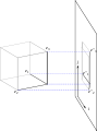
Projection on plane


A pronounced spatial imagination is an absolute prerequisite in technical drawing, as this ability is required both for the creation of perspective drawings and for the correct interpretation of drawings and sketches when reading drawings .
Also, basic geometrical constructions and in particular, the plane geometry of the circle such as tangent and secant , inscribed circle and a radius , the Golden Section or the construction of regular and irregular polygons are among the basic requirements of technical drawing. Both the Pythagorean theorem and parts of Euclid's elements are still used in technical drawing today. An example of the technical application of basic geometric constructions is the perforated rim .
- Penetration, basic construction, views and involutes

Construction of a regular pentagon

Sectional views

Construction of the involute of a circle


Penetrations and thus the course of the curve at the edges of the penetrating bodies play an essential role , for example, in the representation of intersecting bores or bores penetrating into inclined surfaces .
Knowledge of the involute design is required for the visual representation of the involute toothing of a gearwheel (gear theory), since the course of the tooth flanks is determined via the involute.
- Settlement

Development of a cylinder

Sheet metal development funnel shape (wide opening: rectangle, narrow opening: circle)

Development of a sheet metal part
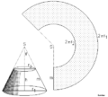
Unwound truncated cone


Special representations such as cone , spherical , pyramid and polyhedron sections , as well as penetrations of various bodies as well as the development of lateral surfaces (e.g. for sheet metal blanks ) play an important role in technical drawing.
Technical drawing in various industries
Depending on the industry, technical drawing makes very different demands on the respective draftsman. Examples of this are rules, norms and degrees of standardization that vary depending on the industry, the representation of technically different objects, assemblies and levels of detail and, last but not least, the often very specific industry knowledge that is required to create the various drawings and at least partially in CAD applications typical for the industries inherently exists.
Technical drawing in mechanical and plant engineering

In machine and plant construction, as well as in their sub-areas such as special mold and tool construction , a completely different drawing program is often used than, for example, in pipeline construction , in fluid technology (e.g. for drawing pneumatic and hydraulic circuit diagrams ) or in automotive , Electrical or furniture industry .
| Automobile drawing with item numbers | position |
|---|---|
|
|
| Source : | The New Student's Reference Work |

Here, too, as in many other areas of technology, the automotive industry can be described as an essential driver of innovation and the development of new technologies, which technical drawing on CAD adapted very early on .
From the technical drawing to the simulation to production


The transition between technical drawing and mechanical simulation in mechanical or plant engineering is fluid. Before the simulation starts, the essential components, connections and joints are modeled on the computer. The model generated in this way is then supplemented by relevant mechanical laws - such as the laws of levers or the laws of fluid mechanics - in order to be able to simulate real processes on the computer more or less precisely according to the respective requirements. The animation shows the basic principle of an organ, how the wind chest is opened by pressing the button and simulates how the air (shown in turquoise ) flows out through the left organ pipe (due to the weight of the bellows) . The wind pressure in the bellows decreases and decreases its height. This simple example shows the close connection between technical drawing, modeling and simulation in computer-aided engineering (CAE) using the example of CFD simulations ( Computational Fluid Dynamics ) as they are common in organ building today.
Similarly, the finite element (FEM) calculation can be based on a 3D model drawn on the CAD system, which serves as the starting point for the subsequent calculations. In addition to the relatively well-known crash simulations in vehicle construction , other load simulations based on technical drawings , such as FEM simulation for manufacturing processes such as injection molding , are also common in mechanical engineering today . In addition to flow simulations, light and indoor climate simulations in architecture and construction can now be carried out by experienced designers, civil engineers or draftsmen. At the same time, technical drawing on the computer creates the basis for CNC-supported production.
Technical drawing in electrical engineering, drive technology, measurement, control and regulation technology
Also in some other areas of technology such as the measurement , control and regulation technology and the general drive technology technical drawing plays in the presentation of specific circuits and circuit diagrams an important role.
A large number of (partially) standardized symbols and symbols are to be used, which apply to hydraulics and pneumatics , for example , but also to electromechanical drives . Some of these symbols can be found in the list of symbols (fluid technology) . Their use can be seen in more detail under circuit diagram (pneumatics) .
As with hydraulics and pneumatics, special rules for the spacing of electrical symbols must be observed when drawing circuit diagrams in electrical engineering and electronics , so that the drawings remain clear and legible. The same applies to symbols and symbols used in measurement, control and regulation technology .
CAD systems commonly used today, which are used to create such circuit diagrams, usually have symbol libraries from which the corresponding symbols can be called up in a similar way to standard parts.
Technical drawing in architecture, construction and urban planning (architectural drawing)

Construction drawings and construction plans are created by architects , civil engineers , other specialist engineers, but also by executing companies. The draftsman profession specializes in creating these architectural drawings.
The type of representation differs in part considerably from the standards in mechanical engineering. The accuracy of construction drawings is also lower due to the mostly larger tolerances on a construction site, so that in Germany dimensions are usually given in centimeters.
- Architectural drawings

Nave (computer drawing)


Industry-specific CAD applications
Although there is still no uniform exchange format across industry and system boundaries, the use of industry-specific CAD software from various manufacturers also contributes to the creation, further development and gradual standardization of exchange formats such as the Drawing Interchange Format (DXF) from Autodesk, the WID format from Dako or STEP (a CAD data format according to ISO 10303 ).
More information on industry-specific, mechanical CAD applications can be found in the list of CAD programs , while the article CAD gives an overview of the industries in which CAD applications are commonly used today.
Computer-aided architectural design (CAAD)

Separate CAD programs have also been developed for architecture and construction , replacing traditional technical drawing by hand. The term computer-aided architectural design (CAAD) are combined programs that help design drawings can be created and technical drawings.
Modern graphics engines of such CAAD programs make it possible to view residential and business premises, bathrooms, factories and other buildings with deceptively real light and shadow effects, and historical buildings that have long been destroyed are created anew in the computer by experts in architectural technical drawing thus serve as a tool for their reconstruction . Such CAAD animations were used, for example, in the reconstruction of the Dresden Frauenkirche , but are also known from the Sagrada Família in Barcelona and many other architectural projects (see also: web links below).
Some universities such as the Swiss Federal Institute of Technology in Zurich have their own CAAD chair .
In architectural informatics , the evaluation and development of standards for CAAD programs is being advanced, with existing standards for technical drawing being incorporated into modern applications for generating architecture . Even modern urban planning has long since ceased to do without the versatile possibilities of this technology , but is making more and more use of it and thus developing computer models of entire cities, including streets , rivers or new airports .
literature
- Hans Hoischen, Wilfried Hesser: Technical drawing . 31st edition. Cornelsen Verlag, Berlin 2007, ISBN 3-589-24130-6
Web links
- Learn technical drawing
- Basics of technical drawing
- Literature and learning program for technical drawing , Christiani
Individual evidence
- ↑ future technical system planners (or technical product designers ) bibb.de
- ↑ a b c Günter Bayerl: Technology in the Middle Ages and early modern times . Konrad Theiss, Stuttgart 2013, ISBN 978-3-534-25232-9 .
- ↑ a b c Hans Hoischen, Wilfried Hesser: Technical Drawing . 31st edition. Cornelsen Verlag, Berlin 2007, ISBN 3-589-24130-6 .
- ↑ Project for CFD simulation for organs ( Memento of the original from June 10, 2008 in the Internet Archive ) Info: The archive link was automatically inserted and not yet checked. Please check the original and archive link according to the instructions and then remove this notice.
- ^ History of technical drawing
- ↑ WorldCAT Internet data format (WID format) ( Memento of the original from March 25, 2008 in the Internet Archive ) Info: The archive link was inserted automatically and has not yet been checked. Please check the original and archive link according to the instructions and then remove this notice.
- ↑ GAUDÍ 21st Century, A virtual reality visit of the temple of the Sagrada Familia, 3D Animation, Barcelona 2002, ISBN 84-89884-35-8