propeller shaft
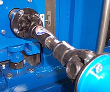
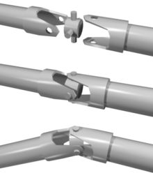
The cardan shaft (named after Gerolamo Cardano ) is a classic version of a cardan shaft combination with one or two universal joints (also called cardan joints). It enables torque to be transmitted in a kinked shaft line. The articulation angle may change during operation.
The term cardan shaft is occasionally also used for shafts with constant velocity joints or for shafts with a hardy disk instead of a second universal joint (e.g. Renault Espace with composite fiber shaft ). These are less efficient than cardan shafts with universal joints.
The name cardan shaft is derived from the universal joints used (see history of the universal joint ).
properties
With a simple universal joint, a uniform power transmission is not possible, especially with larger articulation angles, since the angular speed of the drive axis compared to the output axis is subject to a periodic fluctuation. See: Cardan error
By arranging two universal joints one behind the other, these deviations can compensate each other if the following conditions are met:
- The drive fork of the first joint is offset by 90 ° from the drive fork of the second universal joint (i.e. the axes of the two forks of the intermediate piece are parallel to one another).
- The same articulation angle is present at both universal joints.
- The axes of rotation of the drive, output and intermediate piece lie in one plane.
If the articulation angle is positive and negative, the result is the so-called Z arrangement with parallel axes of rotation at the input and output, which is usually used in vehicles for power transmission between the engine and drive axles. In the W arrangement, both joints bend in the same direction. This constellation is occasionally used in the steering column.
Even if pulsating impulses between input and output are compensated for with double cardan shafts or double universal joints, the oscillation of the intermediate shaft can nevertheless lead to vibrations under unfavorable circumstances. These can be further reduced by using rubber joints or interposed rubber elements.
Technical limits
From a technical point of view, the use of the cardan shaft is limited by several sizes:
- A shaft has a critical bending speed or resonance frequency , above which imbalances lead to impact. This effect limits the maximum speed of the shaft. Therefore, rapidly rotating shafts are made stiff, typically as large-diameter tubes. The critical speed can be increased by using several short shafts with intermediate bearings and additional joints instead of one long shaft. (Disadvantage: noise transmission into the vehicle through the intermediate storage facility).
- With increasing flexion angle and increasing torque, the efficiency of the joints decreases . If the design is incorrect (too great a flexion or too great a transmitted power), the heating can lead to the destruction of the joints. An ideal elongated shaft (flexion angle β = 0 °) theoretically has no losses (η = 100%), which, however, cannot be achieved in practice due to manufacturing tolerances, torsional losses, etc.
Designs and applications

Cardan shafts in cars and trucks
The task of a cardan shaft is to transmit torque. In motor vehicles with a front engine and driven rigid rear axle, the connection between the transmission output and the differential of the driven axle must be designed to be movable. In the transaxle design with a front engine and gearbox on the rear axle, a drive shaft , which is usually designed without joints, connects the engine with the gearbox (e.g. Porsche 924 ). The first car with cardan drive was probably the first car designed and manufactured by Louis Renault in 1898 .
The cardan shaft is usually connected to the output shaft of the gearbox via a Hardy disk , a rubber disk which, in addition to angular compensation, can cushion shocks in the torque transmission. In the case of long vehicles, the front partial shaft is supported with a radial bearing just in front of the universal joint , while one of the articulated joints can be omitted in shorter vehicles.
PTO shaft with two cardan joints
As described above, the transmission of rotation by means of the universal joint is non-uniform if there is an articulation angle at the joint. The rotational frequency specified by the drive is superimposed on the output by a small fluctuation of twice the frequency. With two consecutive cardan joints rotated by 90 ° in relation to one another, the transmission error is canceled out if both joints are equally kinked.
A cardan shaft therefore usually contains two cardan joints and an additional sliding joint, which enables longitudinal compensation. A typical application is the drive of a transversely movable spindle of a machine tool.
One application is PTO systems between tractors and pulled agricultural or other work machines . The second universal joint and the additional sliding joint are necessary here in order to make the torque transmission independent of which movements the towed machine is performing relative to the tractor.

The cardan shaft on motorcycles and bicycles
The cardan shaft on motorcycles is used to transmit torque to the rear wheel. Such shafts often only have a single cross or rubber joint to compensate for the lifting movement of the rear wheel during compression.
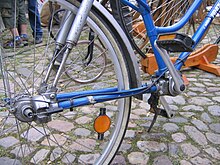
The cardan drive of bicycles is mostly a jointless vertical shaft , see bicycle # Cardan shaft drive to the rear wheel .
literature
- Hans-Christoph Graf v. Seherr-Thoss, Friedrich Schmelz, Erich Aucktor: Joints and cardan shafts . Springer Berlin Heidelberg 2002, ISBN 978-3-642-62601-2 (print).
Individual evidence
- ↑ Kardan theory on the Powerboxer.de page; accessed in September 2016
- ↑ G. Dittrich: Maschinendynamik I , reprint of the lecture series of the Institute for Gear Technology and Machine Dynamics RWTH Aachen, winter semester 1991/1992
- ↑ A hundred years ago, the first car with a cardan shaft rolled in Paris . In: VDI-Nachrichten . Association for the promotion of an open German school network. Archived from the original on September 25, 2010. Info: The archive link was automatically inserted and has not yet been checked. Please check the original and archive link according to the instructions and then remove this notice. Retrieved November 22, 2009.

