Universal joint
A universal joint or universal joint is an angularly movable coupling between two shafts . The angle of deflection between the connected shafts may change during torque transmission.
The combination of (usually two) universal joints with connected shafts is called a cardan shaft .
In contrast to constant velocity joints , universal joints do not transmit angular speed evenly.
Cardan joints, which are not used to transmit rotation or torque, are dealt with in the article " Cardanic suspension ".
history
One of the first more precisely recorded applications was found in the clock of the Strasbourg cathedral from 1354, about which Caspar Schott reported in 1664. With the name Gerolamo Cardano , the movable suspension later known as (mainly in Europe) " cardanic suspension " has become known since about 1550 , whereby Cardano himself wrote that he was inspired by a similar device. Villard de Honnecourt has known a suspension for an oven since 1245, and Leonardo da Vinci suspended a compass in the same way around 1500 .
The English polymath Robert Hooke invented the universal joints in a preform in 1663. He recognized their non-uniform transmission and developed the combination into a double universal joint, which compensated for this non-uniformity by combining two individual joints to form a double universal joint. In the Anglo-Saxon-speaking world, universal joints are still known today as "Hooke's Joint".
Universal joints in their current form with a cross on a tenon date back to Amicus (16th century). The mathematical proof of the non-uniform rotation was presented in 1824 by Jean-Victor Poncelet .
Function and applications

The axes of the compressed intermediate piece cross, but do not intersect.
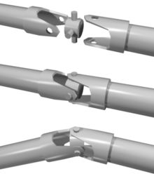
A central part (cross piece) contains two pairs of stub axles crossed at right angles, via which it is articulated to one of the two shafts: The shafts each have a fork-shaped end, the transverse bores of which each include a pair of stub axles. A rarer variant, in which one of the two shafts is articulated inside the central part, is reminiscent of the cardanic suspension (in the case of the cardanic suspension of a gyro compass, there is a third shaft inside, around which the gyro rotates).
A structural unit made up of cardan joints and shaft (s) is called a cardan shaft . This is traditionally used to transmit torque in motor vehicles between the engine / transmission unit and the rear axle . The wave bridges the considerable distance. When the rear axle moves in a springy motion, the cardan joint (or cardan joints) experiences a small amount of flexion.
With a working machine attached to the tractor that drives itself, the deflection between the tractor and the machine is relatively high. The PTO shaft on the tractor is followed by a double universal joint with an intermediate shaft ( double universal joint shaft ).
Cardan failure

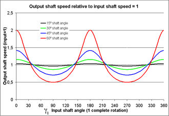
On the left, the angular speed (speed of rotation) of the output shaft of the joint is plotted in relation to the position of the input shaft. The red curve shows that the speed of the output shaft accelerates twice to twice the speed of the input shaft during one revolution and is braked twice again to half the speed if the joint is strongly angled (here by 60 °).
A flexed universal joint causes an uneven transmission of rotation. This means that with a constant rotational speed of the drive shaft, the output shaft does not have a constant rotational speed. This unevenness, which is also known as a cardan error, increases with the flexion angle . The current ratio of the rotational speeds and , also known as the (current) transmission , is at the current angle of rotation of the drive shaft:
- .
- The output shaft rotates twice a little faster and twice a little slower than the drive shaft during one revolution, so that the average speed of the output shaft in turn corresponds to the speed of the drive shaft.
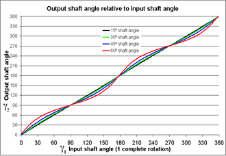
The difference in the angles of rotation is sometimes referred to as the cardan error .
The rotation angle depends on the rotation angle and the flexion angle according to the following equation :
- .
See also
literature
- Graf von Seherr-Thoss, Schmelz, Aucktor: Joints and cardan shafts. Calculation, design, applications Springer, 2002. ISBN 3-540-41759-1
- Siegfried Hildebrand : Feinmechanische Bauelemente , Hanser, 1968.
Web links
- Eugen Klein GmbH: The kinematics of the universal joint
- O. Fischer: Kinematics of the universal joint
Notes and individual references
- ^ A b c Siegfried Hildebrand: Feinmechanische Bauelemente , Carl Hanser Verlag , 1968, page 725
- ↑ Historical data according to “Joints and Cardan Shafts”, see literature
- ↑ Kardan theory on the Powerboxer.de page; accessed in September 2016
- ↑ The following equations and graphics apply to the so-called "zero phase" starting position: γ 1 = 0 °, when the drive-side axis of the cardan cross is in the plane of the two shafts.


