
Vertical shaft
.JPG)


The vertical shaft is a machine element . It has bevel , crown or helical gears at one or both ends so that it can be at an angle to the shaft driving it or the shaft driven by it . Furthermore, a vertical shaft also designates the central drive shaft of a machine , which transmits a rotary movement from a central drive motor to other points on the machine - regardless of the positional relationships between the driven and driven shaft (s).
Line shafts in aircraft engines
The mechanical reliability and the low weight compared to the gear wheel cascade made the vertical shaft widely used in the camshaft drives of in- line and V-engines , which were designed as aircraft engines . Examples are the Hispano-Suiza 8 (1914), Mercedes D III (1915), BMW IIIa (1917), Napier Lion (1918), Hispano-Suiza 12 (1920), BMW VI (1925), Klimow M-100 / M-105 (1935/1938), Daimler-Benz DB 600 (1935), DB 601 (1937), DB 603 (1942) and DB 605 (1941).
Vertical shafts in automotive engineering
The drive of the camshafts for valve control on four-stroke engines is only rarely implemented with vertical shafts. Although these are speed-stable and practically maintenance-free, they are loud and comparatively expensive to manufacture. Helical gears are quieter than bevel gears , but have a worse efficiency .
In the Soviet Union , the W-2 diesel engine was developed at the end of the 1930s and was widely used in the T-34 tank and its successors. The V-engine with four valves per cylinder has two vertical shafts to drive the four camshafts ( DOHC valve control ). The basic design is still used today (2013) in the W-92 S2 engine of the T-90 tank .
From March 1974 to October 1993 the vertical shaft was used as the “term used in technical language” for the standard-compliant designation intermediate shaft in DIN standard 6260, part 3 “ Internal combustion engines ; Parts for reciprocating engines ; Engine control , terms ”and the explanation specified for the intermediate shaft: Shaft to bridge the distance between the crankshaft and the camshaft. This national standard was replaced in November 1993 by the internationally harmonized standard DIN ISO 7967-3, in which the term is completely absent.
Constructions of four-stroke engines with camshafts that take the position of a normal vertical shaft and actuate the valves via link plates ("cam disks") ( Chater-Lea ) and levers are rare. Such constructions are often - technically incorrect - referred to as a vertical shaft with a mounted cam, a control disk or a plate cam.
Use in cars
Even before the First World War , there were automobiles with a vertical shaft drive for the camshaft, such as the Nesselsdorf S 4 (16/20 HP) from 1906. In the 1920s and 1930s, the elaborate design was represented in upper-class, but also sports and small cars: Steiger 10/50 PS (1918), Lancia Lambda (1921), Audi Type M (1923), Austro-Daimler ADM II (1923), Bugatti Type 35 (1924), Mercedes Type 630 (1924), Fiat 509 (1925) , Tatra 17 (1925), Mercedes S / SS / SSK (1926), Horch 303 (1926), Morris Minor (1928), Alta 1100 (1931), MG J-Type (1932), Horch 850 (1935), Audi 920 (1938) and the Crosley CC / CD (1946/1949).
Porsche put the under the internal designation Type 547 developed " Fuhrmann engine " with four vertical shafts and 1.5 liters engine capacity from 1954 in Porsche 550/1500 RS one. With a displacement of 2 liters, the design was still used in the Porsche 904 in 1963 .
Application in motorcycles
It was often used in motorcycle engines, for example from Norton , Nimbus and Ducati , in the latter case in combination with a forced control of the valves; The valves are not closed by valve springs , but by a cam-controlled operating lever. The BMW-RS racing motorcycles also featured boxer engines with vertical shafts. Some of the few current examples are the two-cylinder engines of the Kawasaki W650 or Kawasaki W800 .
Vertical shafts in machine tool construction
Older processing machines (in production engineering ) and special machines (machines for automation tasks) follow a machine concept that provides a central drive shaft through the entire machine: the vertical shaft.
Various machines are driven by several output drives along this vertical shaft. In particular, in automation machines special gear, such as curved or crank are there transmission grown that generate the individual motion required for the task. One characteristic of this machine concept is that all movements are permanently coupled to the main drive. This means that for each angular position of the vertical shaft it is described in which position the individual elements are. A set-up operation on a machine can be implemented using a hand crank on the vertical shaft, for example . Therefore, automation machines based on this machine concept are not very flexible, since changes in production are very often accompanied by changes in the drives on the vertical shaft.
Multi-spindle automatic lathes are a classic application of such drives. For example, large series of turned parts for the mass production of vehicle transmission gear wheels are manufactured on them.
In terms of design, a machine with a vertical shaft is a particular challenge because many kinematic boundary conditions have to be observed. The assembly of the machine itself also requires special knowledge, because this usually involves a lot of time-consuming setting and tuning tasks.
The vertical shaft with several output drives was therefore almost completely replaced by computer control (CNC) with stepper or servo motors . Simple movements that do not have to meet any special dynamic requirements are carried out by pneumatic or hydraulic cylinders .
In machines in which each movement element is equipped with its own drive, the movements are not mechanically coupled, but are usually coordinated by a programmable logic controller ( PLC ). This makes these machines more flexible in their use and also makes many setting and tuning tasks easier.
Vertical shaft in mills
In historical wind and water mills , the vertical shaft transmits the power from the drive (wind impeller or water wheel ) to the grinders and thus takes over the central power transmission from generation to consumption. The vertical shafts were displaced by the rope drives .

Schematic diagram of a water mill:
1: water wheel
2 drive shaft
3: cogwheel
4: crown
5: Bevel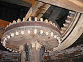
Crown gear in a windmill to transmit the torque from the vane shaft to the vertical upright shaft

Line shaft in a Dutch windmill


Individual evidence
- ^ Motor Klassik, Das Oldtimermagazin, 2/2008, pp. 30–35.
- ↑ Barth, Jürgen; Büsing, Gustav: The big book of the Porsche types . Stuttgart: Motorbuch-Verlag, 2010, ISBN 978-3-613-03241-5 .