Stepper motor
A stepper motor is a synchronous motor in which the rotor (a rotatable motor part with a shaft) can be rotated by a small angle (step) or a multiple of it by a controlled, step-by-step rotating electromagnetic field of the stator coils (stator = non-rotatable motor part) . Stepper motors are also available as linear motors .
positioning
Stepper motors follow the externally applied field exactly and can be operated precisely without sensors for position feedback ( encoder , rotary encoder or similar). They therefore behave similarly to synchronous motors , but generally have a significantly higher number of pole pairs. Therefore, they can be operated more easily than, for example, servomotors (usually DC or synchronous motors with position encoder), which have to be adjusted to the desired position. For a particularly homogeneous course, stepper motors are controlled with a uniform rotating field .
Loss of step
If a stepper motor is overloaded by an external load torque or by the mass to be driven when accelerating or decelerating strongly (i.e. load torque> motor torque), the rotor can no longer follow the rotating field. Steps are skipped and information about the current position of the rotor is lost. With this so-called step loss, the motor jumps back to the previous or next position in the same phase. The mechanical kinetic energy ( inertia ) usually leads to a series of lost steps in rapidly moving magnetic fields. Any step losses that occur add up and then lead to incorrect positioning.
This can be prevented by:
- A position encoder ( incremental encoder or absolute encoder ) measures the exact rotational position within the scope of the quantization deviation . The control (controller) can correct immediately. The engine can be loaded up to the performance limit.
- The control measures the current with every step. If the motor is always operated a little below the load limit (and otherwise switched off with a fault message), a position encoder can be dispensed with.
- In the case of cyclical movements or rotational movements, the position of the motor can be compared with the basic position with an external position pulse from a sensor with every revolution or cycle.
- The overload is prevented.
A gentle start and deceleration is always recommended for higher speeds in order to avoid losing steps. If only the speed is important, not the position, a loss of step can be accepted.
Designs
The stepper motor is differentiated according to its design:
- Reluctance stepper motor
- Permanent magnet stepper motor
- Hybrid stepper motor
- Lavet stepper motor , single-phase stepper motor for mechanical displays such as driving the hands in quartz watches .
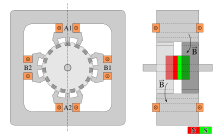
The rotor of the reluctance stepper motor consists of a toothed soft iron core. With this material, the magnetic field disappears after the stator current is switched off . When the current is switched on , the magnetic flux flows through the soft iron core of the rotor. The rotary motion of the rotor occurs because the toothed stator attracts the closest tooth of the rotor, as this reduces the magnetic resistance .
In the permanent magnet stepper motor, the stator is made of soft iron and the rotor is made of permanent magnets , which alternately have a north and a south pole . The permanent magnetic rotor is aligned with the stator magnetic field in such a way that a rotary movement occurs.
Since the reluctance stepper motor does not contain any permanent magnets, it has no cogging torque when the current is switched off, in contrast to the permanent magnet stepper motor. With the permanent magnet stepper motor, the number of poles (and thus the resolution) is limited.
The hybrid stepper motor combines the positive properties of both designs through fine step division and good torque. In this design, a permanent magnet with two toothed soft iron rims at the poles is used as the rotor. The design with two oppositely directed magnets and three toothed rings is also widespread; the advantage is the considerably smaller external magnetic field. The two or three sprockets are each offset by half a step and form a pole piece . Technically, it is a special design of a permanent magnet motor and is only reminiscent of reluctance motors with its toothed soft iron rotor. Almost all stepper motors available today are hybrid motors.
High-torque motors (= high torque ) are often types in which particularly strong rare earth magnets are used for the rotor . A particularly high force density can be achieved in this way.
Parameters
The parameters of a stepper motor are:
- the step angle (or step distance with a linear motor), i.e. the angle for a full step . A full step occurs when the current is switched from one winding to the next.
- the number of phases p (mostly 2, but also 3 or 5 possible)
- the number of steps n per revolution with
- n = 360 ° /
- The number of steps per revolution is a multiple of 2 · p, in the case of two-phase stepper motors that is a multiple of 4, since after 4 steps the same teeth face each other with the same polarity. In the case of linear motors, corresponding steps for the total travel.
- the maximum phase current I; it results from the maximum permissible thermal load I 2 R. It can be higher for a short time in order to achieve a higher torque.
- the ohmic coil resistance R
- the coil inductance L; it is important for the dynamics of the motor and the dimensioning of the freewheeling diodes .
- the torque at standstill (holding torque) for a given current as well as the torque curve with increasing speed; they are dependent on the square of the phase current and the course depends on the driver circuit and its supply voltage.
- the winding connection design ( without center tap, with center tap, with common center tap)
The moment of inertia of the rotor (rotor) is also important - in many applications it forms the main part of the mass inertia and thus determines the dynamics.
The efficiency of stepper motors, on the other hand, is of secondary importance, since the drive power is not important for the typical application as a positioning drive. One often accepts a low efficiency, which is due, for example, to a low rotor inertia, in order to achieve high dynamics.
Electronic step division
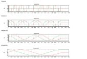
In order to reduce the step angle of a stepper motor, there is the possibility of electronic step division. Two successive phases are not only switched on or off, but in certain stages. This results in two stepped and phase-shifted sine functions. The relationship between the two amplitudes results in steps between the full steps.
The resulting step angle results from:
st is the electronic division factor. st = 2 - half step mode, st = 4 - quarter step mode, st = 8 - eighth step mode, ...
The step division, usually referred to as micro step mode, brings smoother running (more uniform torque) and can deliver a higher angular resolution within the scope of the manufacturing accuracy and the field shape.
Speed and torque

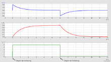
Effective operation of stepper motors requires high rates of current rise and fall. Coils with an iron core, i.e. high inductance L , oppose this with their inductance (see picture). In order to keep the heat development in the coils bearable, maximum phase currents are specified for stepper motors (ohmic heat loss). To achieve a rapid increase in the coil currents after the winding has been switched on, high operating voltages and low numbers of turns (inductances) are required. In order to achieve a faster drop in the current after switching off, the bipolar operation is more suitable - with this the coils (pairs) with an H-bridge are operated alternately in both current directions and the energy stored in the inductance can work against the operating voltage Free-wheeling diodes are fed back there ( see also coil (electrical engineering) ).
Motors that can be operated in unipolar mode have a center tap of the coil pairs and can be operated with single-sided switching transistors. Due to the necessary slower demagnetization, they have poorer dynamic properties, are less effective and are now less common (see also wiring ).
Today's circuits (often integrated circuits ) for the highly dynamic operation of bipolar stepper motors work in chopper operation; Like a switching regulator, they regulate the coil current during each step and can operate low-resistance windings (low inductance) at high operating voltages, so that the current rise and fall are rapid.
The torque of a stepper motor is proportional to the phase current, but the power loss increases with the square of the phase current. Stepper motors can therefore only be overloaded for a short time in order to increase the torque above the nominal value.
The torque curve is at its maximum when the vehicle is stationary and decreases at high speeds. It is characterized by a start-stop frequency below which the motor can follow the electrical steps at a certain phase current value or a certain coil voltage even if there is a frequency jump from or to zero.
In order not to lose a step, the step frequency to increase the speed must run a ramp at least from the start-stop frequency (acceleration and braking). The maximum speed and the torque are improved by the lowest possible inductance / low resistance windings and the highest possible operating voltage. In order to reduce the ohmic losses in the windings, the phase currents are often regulated in such a way that they are reduced when stationary or with uniform movement.
Most stepper motors are two-phase, but there are also three- and multi-phase motors. More than two phases deliver a more even torque and are therefore less prone to build-up of resonance oscillations in the rotor.
Wiring
Stepper motors are always operated together with electronic switches - mechanical buttons or switches can only be used for test and demonstration purposes. Electronic stepper motor controllers generate the necessary phase sequence (sequence) from a digital clock and direction signal in order to generate a rotating field. Stepper motor drivers amplify these digital signals and switch the operating voltage of the motor. The circuit board with the power module is usually located close to the motor in order to keep cable inductance and interference emissions low. With current control, the phase current is also measured and regulated according to the default value. This can be different for standstill or acceleration / braking.
In the unipolar motors that were common in the past, no current control was used - such motors therefore often have higher-resistance windings. In contrast, bipolar motors operated with a chopper control are low-resistance; the current is regulated with a hysteresis switching regulator for each sub-step by switching the coil current on and off very quickly (chopper frequency several 10 kHz). The coil inductance causes the current to rise and fall at this frequency - it lowers the rate of current change required for high speeds and must therefore be low for high dynamics.
For the same reason, the operating voltage of such highly dynamic drives is significantly higher than the nominal voltage of the coils - a significantly higher current circulates in these compared to the total current consumption of the driver circuit.
Due to the switching operation, the power losses in the electronics are so low that all functions including the transistor switch up to a power of about 30 W can be accommodated in a single surface-mounted device (SMD) circuit without a heat sink. L298P, L6219DS, UC3717AQ, A4988, TMC2100 and TMC2208 may be mentioned as examples.
Stepper motors with a different number of phases or coil connection designs cannot be operated on a given control circuit. Stepper motors with separate center taps are an exception ; these can be operated with (nowadays common) full bridge drivers for individual coils. Possibly. the maximum current flow must be reset (measuring resistor).
accuracy
Due to the high number of pole pairs , the rotor of a stepper motor moves forward with only a small angular offset with each externally specified step. 24 to 200 steps per revolution are common, but stepper motors with 400 steps per revolution are now also available. A number of pole pairs of 50 in a two-phase motor in full step mode results in 200 steps per revolution, i.e. 1.8 ° full step angle. A resolution of less than 0.1 degrees can be achieved through microstep operation. The step accuracy is usually in the range of a few percent.
application areas

Typical areas of application are printers , especially matrix printers , or driving the read / write head in a floppy disk drive . Due to their high accuracy, they are also used in computer-controlled machine tools for positioning the tools and especially in 3D printers . Due to the constantly falling costs for the control electronics, they are also increasingly used in the consumer goods sector. Today, up to 50 stepper motors are used in motor vehicles of the medium and high-end categories, the actuation of the many flaps of an automatic heating and air conditioning system is an example of this.
The double stepper motor shown on the right is intended for use in an instrument cluster and can operate two hands on one shaft, like the hour and minute hands on a clock. The partially dismantled left motor acts on the hollow plastic shaft, the right on the steel shaft.
Stepper motors to about 1 k W to be used economically.
standardization
Size
The US National Electrical Manufacturers Association (NEMA) has standardized a number of stepper motors. They all work at 200 steps per revolution. They are numbered consecutively in the number range NEMA1-2011 reserved for "Motors and Generators". The data sheets can be requested from the association for a fee (as is the case with DIN, for example ).
As an American institution, NEMA traditionally uses the “English” system of measurement “inches”, while in the western world almost only the metric system is used. When converting from inches to millimeters ( 1 "= 25.4 mm ), rounding inaccuracies and errors occur. Therefore, the bolt circles in some dimension sheets can differ slightly. However, the deviations are usually so small that they are covered by the general tolerances.
Known standards are z. E.g .: no., Flange dimension, typical holding torque
- NEMA 08, 20mm x 20mm, 0.036Nm
- NEMA 11, 28 mm x 28 mm, 0.1 Nm
- NEMA 14, 35mm x 35mm, 0.3Nm
- NEMA 17, 42 mm x 42 mm, 0.5 Nm
- NEMA 23, 56 mm × 56 mm, 2.0-4.0 Nm
- NEMA 34, 86 mm x 86 mm, 4.5 - 8.0 Nm
The holding torque (here in the NEMA 23 example approx. 2 Nm corresponds to 270 Oz-In) is also often specified in the "English" system of units.
Protection class
The degree of protection (against dirt, water, etc.) is in the internationally recognized " I nternational P rotection" ( IP specified).
literature
- Günter Springer: Expertise in electrical engineering. 18th edition. Verlag Europa-Lehrmittel, Wuppertal 1989, ISBN 3-8085-3018-9 .
- Gregor D. Häberle, Heinz O. Häberle: Transformers and electrical machines in power engineering systems. 2nd Edition. Verlag Europa-Lehrmittel, Haan-Gruiten 1990, ISBN 3-8085-5002-3 .
- Gerd Fehmel, Horst Flachmann, Otto Mai: The master's examination in electrical machines. 12th edition. Vogel Buchverlag, Oldenburg / Würzburg 2000, ISBN 3-8023-1795-5 .
- DW Jones: Control of Stepper Motors. (on-line)
- D. Austin: Generate stepper-motor speed profiles in real time. In: EE Times -India. January 2005 ( digitized version )
See also
- Brushless DC motor (brushless DC motor)
Web links
- Good functional description and practical tips
- Everything about the stepper motor
- English-language introduction to the stepper motor
- German-language technology blog about stepper motors
- Animation of stepper motors and BLDC motors with and without sensors
Individual evidence
- ↑ Beckhoff, Application Note DK9221-0210-0014: Stepper motor (PDF; 275 kB), section General information on stepper motors


