
Mold making


Mold making is the generic term for the production of molds which are required for the production of cast parts made of both metal and plastic.
The following article essentially describes the manufacture of molds that are used to produce plastic parts. The use and manufacture of molds for the production of metal parts is described in the article casting (metal) .
Basics
Permanent form and lost form
Permanent forms are forms that can withstand numerous and multiple casting processes. They are used for series production .
- For large quantities there are permanent molds made of steel for plastic casting or metal die casting. Other permanent forms consist of fireclay in metal casting, concrete in concrete and artificial stone casting , and others.
- For small quantities (small series) there are molds made of wood , plaster or similar material. This z. B. glass fiber reinforced plastic parts or castings are made.
Lost forms are destroyed during or after casting
- Created in industrial casting from sand (with binding agents) according to a model
- a specialty is the lost wax process (e.g. small parts for medical technology)
Mold components: die, core, cavity
Metal molds may consist of several hundred individual parts ( mold components exist). These items can be molded parts or purchased standard parts and standard parts to be.
- A metal mold consists of at least one die (“mother mold ”), which forms the negative of the outer mold for the mass part to be produced.
- If the component is to have a cavity or a concave shape, a core is required as an inner shape. The core can be removed when the mold is open and there are no undercuts to prevent removal. Otherwise it remains in the material, is dissolved chemically or by heating or mechanically destroyed and then removed. If, for example, a core made of styrofoam with clay is used as the casting material, the core outgasses during firing and only a small opening is necessary to allow the gas to escape.
The cavity remains between the core and the die as the hollow shape to be filled. The entirety of the form is the model . This term is not common in all casting techniques.
In the case of pressure and compression molds, one also speaks of patrix (counter-mold) .
Tool construction
Most mold assemblies are divided into the nozzle side and the ejector side . The negative contour of the casting is present as a cavity in both halves. The casting machine moves these two mold halves apart after the casting process (injection) and solidification. The molded part remains in the ejector side and is ejected with the separate ejector device. The contour of the molded part does not allow any undercuts in the opening direction. If the contour still has to have undercuts, additional slides are installed which are retracted before the ejection process.
Parts of a typical shape are:
- Clamping plate nozzle side
- Mold plate nozzle side
- Mold plate ejector side
- Spacer strips for the ejector plates
- Ejector plates with the ejectors
- Clamping plate ejector side
- Connections for the cooling holes
- Hot runner or cold runner nozzle
If necessary, slides and various attachments, such as type plates, transport brackets, cycle counters, etc. are added.
Artisanal forms
Historic stone cast
Casting in stone is a historical way of making objects out of metal. Thousands of years ago, people developed an impressive skill and were able to produce the finest objects.
The materials for stone molds were mostly easy to work stone types such as sandstone or soapstone. Granite forms are extremely rare to find.
The negative is worked into the stone by chiselling, scraping or carving. The liquid metal is filled into the mold and solidifies there.
There are four types of stone pouring:
- The first is open hearth pouring . Only one mold half is used here. A strong reaction with oxygen occurs through the open side, which leads to the formation of bubbles on the metal and makes it rough and porous.
- A second variant is the concealed hearth casting , whereby one mold half is put together with a blind half. This prevents excessive oxidation of the melt. Since one half is blind, pass holes, locks and the like are not necessary. If there are two halves with a shape negative, these must be worked into the stones to prevent the two shapes from shifting. These castings can also be recognized by the cast seams that arise along the mold division.
- Another variant is called core casting , which is used to manufacture objects with cavities.
- The fourth and last type is overlay or composite casting . This is a second infusion on a semi-finished product. This technique is also used to repair or repair defective or unsuccessful pieces. Bonded or overlay casting was also used in the lost wax process .
Modern forms
Molds for small quantities are mostly made from glass fiber reinforced plastics ( GRP ), less often from carbon fiber reinforced plastics ( CFRP ). Such molds are worn out after about 10-200 components have been produced. They are particularly useful for the production of complex and large parts, for example in boat building. GRP molds are usually made by hand by placing thin glass fiber mats around a master model (often a solid polystyrene core) or around a sample component and hardening them. This creates a so-called negative shape. During the manufacture of the component, the material to be shaped is attached to the inside of the mold, which results in a smooth outer surface. A positive form (also known as a core), on the other hand, is an image of the component to be manufactured; the material to be molded is applied to the outside as described above, making the inside surface smooth. The production of the mold and the components is possible using the same process and often only differs slightly in practice.

Steel mold construction: permanent molds made of steel
For large quantities there are permanent molds made of steel for injection molding (plastic) or die casting (metal). Here one also speaks of steel mold construction , which is closely related to tool construction .
More wear-resistant forms are usually made of hardened or tempered tool steel or hard metal . The mostly very precise shape contours are incorporated with the help of various machine tools according to the design drawing and NC data, sometimes by hand. This makes the production of a form of expensive, but for the production of components in large quantities, this is from a certain lot size (minimum quantity) cheaper and faster than the parts production without forms (for example with CNC - milling ).

Mostly standardized mold bases of serve as the basis for the steel mold standard parts manufacturers . Depending on the area of application, the mold assemblies can vary in size and design.
Standard shapes
The standard forms are suitable for a wide range of applications in mold making. The superstructures are modular. This means that the plates can be freely selected in terms of thickness and material from the tool structure.
Baking molds
The baking molds have a ready-to-use slide that covers the entire length. This type of mold construction is therefore suitable for components with large undercuts.
Alternating forms

Shortest set-up times are required when changing tools, especially when manufacturing prototypes and small series. With the interchangeable molds, the mold structure remains on the machine, with only the interchangeable inserts on the nozzle and ejector side being exchanged.
use
When using a mold, a misshapen material is brought into the desired shape by the tool. The material can be, for example, soft mats, granules or a melt. The material is introduced into the tool (i.e. the mold) using different methods :
- Mineral casting
- Injection molding ( processing of plastic ) ( thermoplastic , duroplastic , elastomer )
- Die casting (processing of non-ferrous alloys , e.g. aluminum , magnesium and zinc )
- Transfer presses
- Fiber syringes
- Compression molding
- Extrusion
- Drop forging (processing of metal )
These processing methods can be combined with one another. Completely different or similar materials can also be combined and processed in successive processes.
- Construction drawing of a plastic injection molding tool

Ejector side (left) and nozzle side (right)

- Photos of a die casting and an injection molding tool
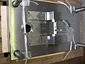
Die-casting tool for aluminum, nozzle side

Die-casting tool for aluminum, ejector side
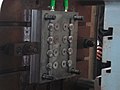
Injection molding tool for cosmetic bottle caps


Solidification of the material
The material introduced into the mold must solidify before it is removed again. Depending on the nature of the material, this is done by cooling or with the help of heat treatment. Hardening in a vacuum chamber (see vacuum casting ) is also possible.
Demolding
Demoulding refers to the removal of the hardened material from the mold. How this is done depends on a number of factors. In some cases, complicated mechanisms are used to remove a part from this shape again. The most complicated mechanisms are used in injection molding and die casting . In addition to common ejectors, flat ejectors or scrapers, slides or inclined ejectors are used. A particular difficulty is the demolding of three-dimensional forms, which because of their design do not allow easy removal in one direction; as an example, imagine a three-quarter ball. Threaded or collapsible cores are used here. In some cases, the core can simply remain in the part. The demolding variants can also be combined with one another.
shrinkage
So that the various materials can be processed in mass production, they have to be heated or heat is generated during processing . As it cools down, the final workpiece becomes a little smaller. This reduction is called shrinkage (shrinkage). The shrinkage depends mainly on the material used, but also on the process used , its processing and other factors. Shrinkage must be taken into account when making a mold. This means that a contour (every dimension) has to be enlarged by a certain percentage. This is taken into account in the design . In the case of very different and asymmetrical contours, what is known as pushing the contour is often necessary. This improves the dimensional accuracy with different longitudinal and transverse shrinkage.
Surface texture
A mass part always has a very specific surface quality and roughness . This surface quality must be taken into account when making a mold. Depending on the needs of the end user, the surface of a mold is polished , according to a certain pattern structure (z. B. etching , laser texturing or sand blasting ) or the applied manufacturing process of the corresponding machine tool left.
Important functions in one form
Temperature control
As a rule, the mold must be brought to a temperature adapted to the process and material. When processing thermoplastics , the mold must be colder than the melt so that it cools down and solidifies in the mold. The cooling of a mold essentially determines the cycle time in production and thus the costs of the series part to be produced. The better the cooling, the shorter the cycle time.
With thermosets and elastomers , the tool must be warmer than the molding compound so that it crosslinks in the mold .
In order to achieve temperature control, bores are mostly made in the tool in several complicated cycles, as evenly as possible and close to the mold section. A liquid medium (e.g. cold water or warm oil) flows through this during the manufacture of the injection molded parts. The interface is usually released using quick or multi-couplings. In doing so, the forward and return lines should be unmistakable and a permanent and process-reliable solution should be selected.
The following can be influenced with mold temperature control:
- Cycle time (and thus the costs of the molded part to be manufactured)
- Part distortion or shrinkage behavior (quality of the molded part to be produced)
- Surface properties of the molded part (e.g. gloss or matt for plastic molded parts or aluminum alloys)
- Quality at the point of the injection point
- Tool life
A special form are inserts for conformal temperature control using cooling channels and a cooling medium to further reduce cycle times.
Sprue system

Under sprue is meant to DIN 24450 the portion of the molding, is not part of the molding. The mold's sprue system is used to receive the molten molding compound coming from the plasticizing cylinder and to guide it into the mold cavity. The sprue, in particular its shape, its dimensions and its connection to the molded part, influences the mold filling process and thus largely the quality of an injection molded part. The design based on purely economic aspects (e.g. fast freezing and short cycle times) is contrary to the quality requirements in many cases, especially for technical parts.
The sprue or the sprue system usually consists of several segments. This is particularly clear with multiple tools. The sprue system consists of:
- the sprue cone, also called sprue pin or sprue rod, which takes over the plastic molding compound directly from the nozzle that closes the plasticizing cylinder and which leads to the tool plane on which it is generally perpendicular. In the case of simple tools, it often forms the entire sprue system alone. One then speaks of the so-called bar sprue.
- the sprue (s), also called sprue spider or sprue manifold, which connects the sprue cone with the sprue or bars. Its essential task, especially in the case of multiple tools, is to distribute the melt in such a way that material of the same state (same pressure and same temperature) fills the tool cavities at the same time.
- and the sprue, the cross- section of which is called the gate at the entry into the mold cavity (DIN 24450). The term connection is also common for this .
The sprue system is usually hardened in order to be able to withstand temperatures, pressure and abrasion (wear and tear). It is often also coated to ensure better flow properties.
The material in the sprue usually solidifies with the molded part and usually has to be removed mechanically. It is either waste or it is recycled . Furthermore, the volume of material to be provided per casting process increases by the sprue volume, which results in an increased need for machine capacity. According to the geometry, a distinction is made between:
- Bar or cone sprue: see above
- Tape or film sprue: Here, the entire width of the molded part is cast in order to minimize tension and warpage.
- Shield sprue : In the case of rotationally symmetrical , the entire end face is usually cast, so that an equally rotationally symmetrical, umbrella-like sprue is created.
- Ring or disc gate : Cylindrical components are often filled from the inside via a disc-shaped gate.
The following types of sprue are separated automatically:
- Tear-off point gate: The sprue is designed in such a way that a thin predetermined breaking point is created at the gate, which tears by itself when demoulding.
- Tunnel sprue: Here a cutting edge separates the sprue from the molded part when the tool is opened.
Casting without a sprue is also possible. This prevents the material from solidifying in the sprue so that it can be pressed into the cavity and used for the next molded part. With thermoplastics, the melt in the sprue system must be kept above the mold temperature so that it remains liquid ( hot runner system ). In the case of thermosets and elastomers, the sprue system must have a lower temperature than the mold in order to slow down the crosslinking reaction ( cold runner system ). With needle shut-off nozzles in the gate area, it is possible to close the sprue system during demolding, but there are also open nozzle systems.
Ejector
The ejector unit, or also the ejector package, is used to demould an injection-molded or cast part. It essentially consists of an ejector base plate and an ejector retaining plate as well as the number of ejectors, which are usually round, depending on the part contour. The ejector pins, which are held in place by a collar on the holding plate, are pushed forward via an ejector bolt, which is connected to the base plate and the hydraulic system of the machine, in order to eject or eject the part from the mold.
In the case of more complex molded part contours, the ejector pin can also contain more complex functions such as angled ejector, contour ejector, sleeve ejector or flat ejector. The ejector package is usually secured by back pressure bolts that force the package back when the mold is closed, if it has not been withdrawn, in order to prevent errors in the program sequence and thus damage to the expensive mold sections. Limit switches are also used to check the end position of the package before the closing process. Depending on the injected or cast part, different materials with coatings and heat treatments are used for the ejectors.
Slider
Slides are used to demold parts that cannot be demolded in the normal demolding direction. This means that the injection-molded or cast part cannot be demolded by simply opening the mold in the so-called parting line. These areas are called undercuts .
Such undercuts on the molded part can make a shape much more expensive, even if they are only very small. The position of the undercut, which indicates the direction of demolding, is a determining factor in the effort required to manufacture a tool.
Slides are operated either mechanically by diagonal pull bolts while the mold is being opened or hydraulically in order to free the molded part or cast part from the undercuts.
Manufacturers of standard parts also offer so-called ready-to-use jaw forms. This type of mold construction has the advantage that the slide covers the entire length of the mold. This means that complex components with large undercuts can be demolded.
Clamping
In order to fix a mold in the injection molding machine, a clamping plate is usually used on both sides . This is usually provided with clamping grooves that are matched to the corresponding machine type. Another possibility are protruding clamping plates, which are clamped on the machine using power clamps.
Today's production demands ever faster changes of products and thus smaller series that are manufactured (just-in-time). A quick-release system can be useful for the associated frequent changes of the mold on the production machine. This simplifies the clamping and the quick connection of cooling, hydraulics or pneumatics .
Leadership and final centering
The guide serves to center the two mold halves against each other during the closing process. Basically the guide pillars are installed on the nozzle side and the guide bushes on the ejector side. As a standard, no 4 identical guide elements (guide columns and bushes) are used in a mold structure, but 3 pieces of the larger diameter and 1 piece of the smaller diameter. This has been tried and tested in mold making for years, because it can prevent incorrect assembly of the two mold halves.
In the parting line, end centering devices are also attached, which guarantee that the two mold halves are exactly centered to one another when closed. This prevents a radial offset of the two tool halves. As a result, among other things, the wall thicknesses of the injection molded parts are different. This is also called a shape offset.
The so-called flat guide is a combination of guidance and end centering. This is mounted either horizontally or vertically in the parting plane.
Thermal insulation panels
In order to thermally isolate the mold structure from the injection molding machine, heat protection plates are inserted between the clamping or mold plate. This enables shorter cycle times and lower energy costs to be achieved.
Especially in the area of processing thermosets and elastomers , where the tool is heated after the injection process, ribbed heat protection plates are also attached outside the mold plate. Here, too, the goal is to shorten the cycle time and save energy costs.
Microforming
The Microsystem Technology is a market with one of the highest growth rates in the world and has now found its way from the laboratory into production. This advancing miniaturization of components poses new challenges for tool and mold making.
Milling plays a key role in the manufacture of microforms and tools. Compared to other methods such as B. grinding, eroding, lasing or manufacturing processes from semiconductor technology, it has various advantages:
- Machining of tool steels
- Great freedom of geometry
- Use of existing CAD / CAM infrastructures
- Low environmental impact from operating resources
- Relatively low investment
Additional functions
Customers are increasingly expected to have additional functions that are only indirectly related to the actual tool (form):
Feed or handling system
A handling system is required to remove the injection-molded or cast parts or to add inserts. It is used for automation in production, including for shift operation .
Deburring tool
At the separation of the two mold halves, a burr (mold separation burr) may develop. If necessary, this is removed together with the sprue system and the overflow by means of punch deburring.
Engineering
The current development of products requires parallel work between customer and tool manufacturer . This is called simultaneous engineering , which shortens the development time for products. Part or all of the development work can also be carried out by mold construction.
See also
literature
- Rainer Dangel: Injection molding tools for beginners . 1st edition. Carl Hanser Verlag, 2015, ISBN 978-3-446-44352-5 .
- Harry Pruner: Injection molding tools compact . 1st edition. Carl Hanser Verlag, 2012, ISBN 978-3-446-42750-1 .
- Heinrich Krahn, Dieter Eh, Harald Vogel: A thousand construction examples for tool and mold making in injection molding . Carl Hanser Verlag, Munich / Vienna 2008, ISBN 978-3-446-41243-9 ( limited preview in the Google book search).
- Peter Unger (Hrsg.): Gastrow - injection molding toolmaking in 130 examples . 6th edition. Carl Hanser Verlag, Munich / Vienna 2007, ISBN 978-3-446-40389-5 ( limited preview in the Google book search).
- Thomas Munch, Dr B. Lantz: Consistent optimization of the injection molding process . An SGP manual. 2009. ISBN 978-3-8370-7081-1
Web links
Associations