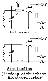
Anode rectification
The anode rectification is a historical process for demodulation of amplitude-modulated signals using an electron tube in which the demodulated signal is first removed at the anode. In the narrower sense, the anode rectification is referred to as rectification at the cut-off point of the grid (bias) voltage. The terms "directional amplifier" and "steep audion" are also used.
Modulation and demodulation are the processes that make radio transmission and thus radio transmission possible.
effect
The signal source with no DC components in the schematic diagram is not loaded by the tube. So the quality of an oscillating circuit that is connected to it , which is used as a signal source for audions, is only insignificantly impaired (see grid current ).
The positive half cycle of the input signal leads to a positive half cycle of the anode current and thus to a negative half cycle of the anode voltage. The negative half-wave of the input signal blocks the tube in an ideal model and thus has no further effect. This ideal case is only roughly achieved in practice; rectification still takes place.
A tube-dependent threshold value means that the cut-off point and the zero crossing of the sinusoidal signal do not match. There is therefore a level of signal below which no rectification takes place. In principle, it is immaterial whether the signal does not overcome the threshold value or whether it is transmitted linearly below the threshold value and is therefore also not rectified. Mostly it is assumed in the model that the threshold value is a voltage.
This threshold voltage, which is essential for the refined model of the rectification, results in the case of anode rectification as the difference between the voltage, which is assigned to the blocking point in the characteristic curve, and the bias voltage . This threshold voltage is therefore subject to larger deviations from the nominal value ("zero crossing" of the sinusoidal signal).
Due to the penetration of the anode voltage through the grid onto the space charge around the cathode, the characteristic curve shifts with a changing anode voltage. In the vicinity of the blocking point, the voltage drop at the load resistor caused by the anode current can be neglected, and the specific position of the characteristic is determined by the operating voltage .
The dynamic range
The modulation range of the tube is limited on the one hand by the cut-off point and on the other hand by the occurrence of saturation at which the cathode cannot deliver any further electrons under the given operating conditions.
In the case of the "half-wave rectification without charging capacitor" model, the mean value is included . This means that the maximum possible LF signal can be around a third of the dynamic range.
In comparison, the high-frequency signal for grid rectification must fit completely into the dynamic range, i.e. it must only be about half as large. The mean value, which determines the maximum volume, is, however, half and is therefore significantly greater than for anode rectification. The grid rectification is therefore significantly more favorable in terms of overall gain and more favorable in terms of controllability than anode rectification.
Waveform
The signal curve of the anode rectification, referred to as a directional amplifier in the picture, corresponds to a half-sine wave only in the ideal case. The zero crossing assumed in the model or the effective threshold voltage are relatively uncertain - they depend on the model and type of the tube as well as on the operating voltage and the aging.
The sub-arcs of the sinusoidal signal are distorted by the rounded course of the characteristic in its lower part. This course is clearly visible in the right part of the picture. A comparable smooth transition, however, is typical for all rectifiers, but is particularly pronounced in electron tubes .
The described distortions are included in the mean value of the deformed arcs of the sinusoidal signal. This mean value is the resulting demodulated signal.
Distortions
The grid rectification is used again for comparison, which is the "one-way rectification with charging capacitor" model with regard to demodulation. The current flow angle is small here, it is in the immediate area of the maxima. Therefore, the above-mentioned distortions do not matter as long as the high-frequency signal is large enough. This is normally the case because the modulation depth, which determines the volume, rarely reaches values close to one.
In the case of grid rectification, the demodulated signal is mapped onto the part of the characteristic curve that is “more linear” than the lower part that is used for anode rectification. This figure is shown in the right part of the picture.
The grid rectification is not only more favorable than the anode rectification with regard to the dynamic range and the gain, but also because of the lower distortion.
Anode rectification and feedback
The operating point lies in a range in which the steepness of the characteristic is lower. The increase in the input signal achieved through feedback therefore leads to an increase in gain and thus has a self-amplifying effect. In practice one speaks of a “hard use of feedback”.
Obviously, grid rectification has an advantage in this respect as well.
Automatic grid tensioning
The anode rectification is also possible with a cathode combination Ck / Rk, which brings about an automatic grid pre-tensioning, that is, an operating point stabilization. The voltage drop across the cathode resistor Rk creates the grid bias.
However, this solution has the disadvantage that with increasing signal level the mean anode current also increases and with it the bias voltage. The error described above in connection with the threshold value occurs systematically in this case.
The operating point is shifted into the steeper range with a slight delay due to the automatic pre-tension generation, which increases the "hard use of feedback".


