Grid rectification
The grid rectification , including audio rectification or Gitterdemodulation called, becomes the demodulation of amplitudenmodulierteren uses signals from radio transmitters. First, the grid rectification was operated with a triode , an electron tube with three electrodes. It was used in low-cost radio receivers such as the Audion until the middle of the 20th century and today has hardly any areas of application worth mentioning.
The circuits for grid rectification and tip clamping are the same. The circuits for half-wave rectifiers and envelope curve detectors are also used for AM demodulation, but have different circuitry designs.
Function description
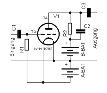
The circuit diagram opposite shows a grid rectification with a triode. The amplitude-modulated received signal is fed to the triode's grid on the left via an RC combination (grid combination). The demodulated and amplified baseband signal is applied to resistor R2. C2 and the internal resistance of the triode together form a low-pass filter. A low frequency amplifier is connected via C3.
The grid combination is available in different versions. The resistor R1 can be connected in parallel to the capacitor C1, see Audion .
The specialty of this circuit is that the triode performs two functions:
- The control grid behaves like a tube diode to the heated cathode of the tube . Negative charge carriers ( electrons ) can easily get from the cathode to the grid, but not in the opposite direction. This results in peak clamping , which is used to demodulate the amplitude-modulated signal.
- It serves as an amplifier and amplifies the weak signal from the input to a level that can be reproduced via a loudspeaker, for example. The property of the electron tube is used here, that the grid voltage controls the current between the cathode and anode of the tube.
Equivalent circuits
In principle, when the carrier is not suppressed, AM demodulation can be achieved with little circuitry through rectification and subsequent low-pass filtering . The received input signal can be rectified in two ways:
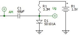
- As a tip clamp as shown in the adjacent figure. The amplitude-modulated input signal is fed in on the left. The modified RF signal can be tapped on the right. The semiconductor diode represents the grid and cathode connection of the triode in order to illustrate the function of the grid rectification.
- As a half-wave rectifier , as shown in the second illustration. Input signals of incorrect polarity are blocked and not passed through to the output.
In both circuits, a combination of a resistor R and capacitor C is used to produce a first-order low-pass filter with the 3 dB cutoff frequency of f = (2π RC ) −1 and to suppress high-frequency carrier components at the output. This low pass is also referred to as a grid combination in grid rectification and the dimensioning of the two components depends on the base bandwidth to be transmitted , with the maximum frequency component f max , and the degree of modulation m used . In practice, the product of R and C becomes slightly smaller than:
elected. For example, for AM radio transmissions with f max = 4 kHz and m = 50%, the value of 80 µs must not exceed, which requires a capacitor of around C = 100 pF with a resistance value of R = 800 kΩ .
Waveform
The picture opposite shows the signal curve of the amplitude-modulated signal at the input of the half-wave rectifier in green and the demodulated, low-frequency signal in red at the output after the low-pass filtering. The low-frequency signal corresponds to the envelope .
The low-pass filter is intended to suppress the high frequency at the output of the rectifier, but is not intended to distort the modulated low-frequency signal. If the cutoff frequency of the low pass is too high, the low frequency is overlaid with high frequency, see residual ripple . With amplitude demodulation by means of rectification for broadcasting purposes, the ripple is around one percent. If the cutoff frequency is too low, the demodulated signal can no longer follow the envelope and additional non-linear signal distortion occurs, which is expressed by the distortion factor .
application
The grid rectification was used especially before 1945 in the people's receivers and after 1945 in the industrially manufactured single-circuit receivers , but also in superheterodyne receivers . The corresponding functional group of the receiver is called Audion . For playback via a loudspeaker, an additional tube was sufficient as an audio amplifier. The two tube systems were also combined to form composite tubes .
Web links
swell
- ^ Walter Conrad: Basic circuits of radio technology . 4th edition. Fachbuchverlag Leipzig, Leipzig 1958.
- ↑ Otto Zinke , Heinrich Brunswig: High Frequency Technology, Volume 2 . 4th edition. Springer Verlag, 1993, ISBN 3-540-55084-4 , pp. 503-506 .


