
BLEAG 1 to 4
| BLEAG 1 to 4 | |
|---|---|
 Locomotive 2 as a memorial in Karlsruhe, 2006
|
|
| Numbering: | 1 to 4 |
| Number: | 4th |
| Manufacturer: | mechanical: Herbrand wagon factory electrical: AEG |
| Year of construction (s): | 1910/11 |
| Retirement: | 1965 |
| Axis formula : | Bo'Bo ' |
| Gauge : | 1000 mm ( meter gauge ) |
| Length over buffers: | 10,600 mm |
| Width: | 2,700 mm |
| Trunnion Distance: | 5,000 mm |
| Bogie axle base: | 1,600 mm |
| Total wheelbase: | 6,600 mm |
| Service mass: | 30,500 kg |
| Wheel set mass : | 8,200 kg |
| Top speed: | 30 km / h |
| Continuous output : | 4 × 50 kW, later 4 × 60 kW |
| Driving wheel diameter: | 950 mm |
| Wheel diameter: | 1,000 mm |
| Power system : | 8,800 V 25 Hz ~ |
| Power transmission: | Overhead line |
| Number of traction motors: | 4th |
| Brake: | Hardy brake |
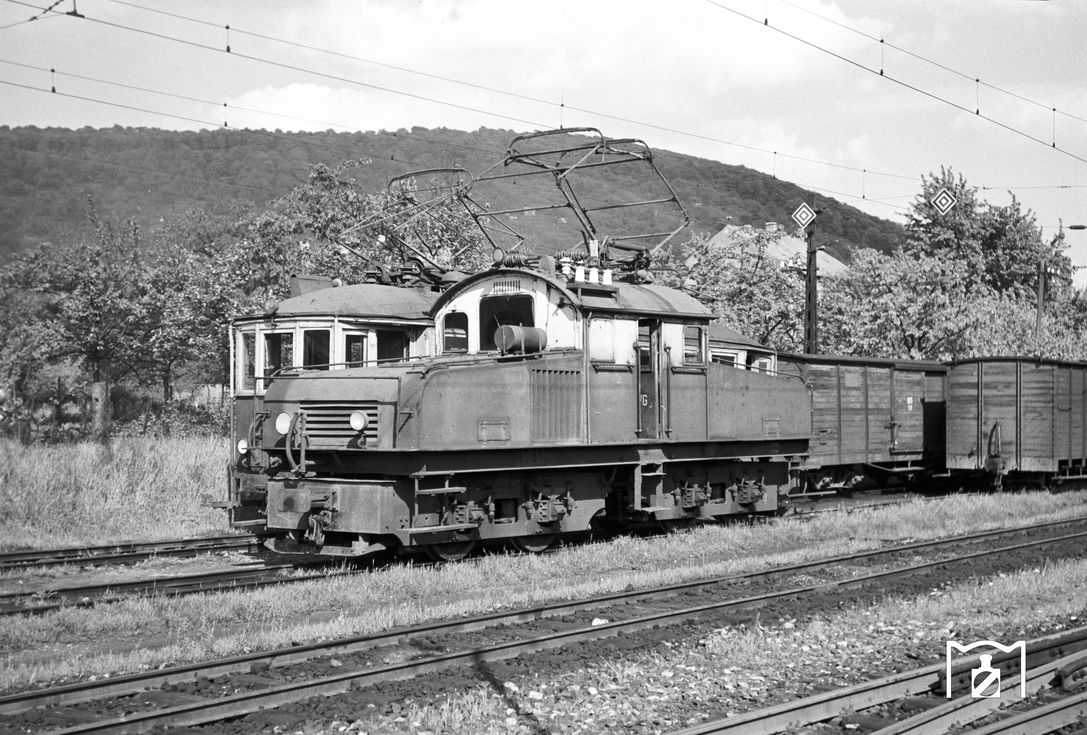
The BLEAG 1 to 4 were four four-axle electric locomotives of the Badische Lokal-Eisenbahnen AG (BLEAG), which were used on the originally meter-gauge Albtalbahn and its branches. The vehicles were in service until around 1964. Locomotive number 4 was a test vehicle for two-system operation on the Alb Valley Railway.
history
After the Albtalbahn was converted for operation with alternating current 8.8 kV 25 Hz, it procured four heavy four-axle locomotives, which were supplied by the Herbrand wagon factory and AEG . The locomotives performed their service on the main line Karlsruhe Albtalbahnhof - Bad Herrenalb as well as on the Ettlinger Seitenbahn , the branch line Busenbach - Ittersbach and initially on the adjoining section Ittersbach - Pforzheim . The locomotives provided both passenger train service and freight traffic, which was subject to fluctuations in quantity.
The Albtalbahn was hit by low-flying attacks during World War II . Nevertheless, the locomotives survived the war and then continued to work, especially for heavy trains that required steam leader . The locomotives were more powerful than the railcars. They were in use until the line was changed to standard gauge and were retired by 1964.
construction
Original version
The electrical equipment consisted of the assemblies power transformer , vehicle control, Winter-Eichberg motors , auxiliary systems and vehicle control. The transformer received the working current from the contact line via the pantograph, the roof entry insulators and the high-voltage chamber. The pantograph was originally equipped as a pantograph with individual contact strips , from 1930 with horizontal end pieces and double contact strips. The transformer had different taps for the six speed steps, the different driving positions of the vacuum pump for the Hardy brake as well as for lights, locomotive and train heating as well as for the auxiliary systems such as bells, headlights and oil switch pump. In addition, the locomotive had two excitation transformers, each on a motor set and used to reduce armature currents.
The locomotives were equipped with four Winter-Eichberg engines, which were designed as tatzlager engines and ran at speeds of up to 750 rpm. In the driver's cab there were drive switches, directional reversers and brake controllers for the Hardy brake. The individual speed levels were selected with the drive switch, and the power transformer tap for the drive motors was controlled via a contactor control.
Two-system test locomotive
| Technical data of the two-system locomotive | |
|---|---|
| Hourly output: | 4 × 115 kW |
| Top speed: | 50 km / h |
| Hourly traction: | 4.2 t |
| Starting tractive effort: | 6.2 t |
| Continuous tensile force: | 3.3 t |
| Number of pole pairs: | 3 |
| Weight of a motor without gearbox: | 1.06 t |
| Gear ratio: | 1: 7.77 |
| Outside diameter of a motor: | 600 mm |
| Rated power of the transformer 25 Hz: | 320 kVA |
| Rated power of the transformer 50 Hz: | 380 kVA |
| Weight of a transformer: | 2.2 t |
When the AEG carried out studies to test dual-system locomotives in the mid-1950s, the Albtalbahn with its branch line Busenbach – Ittersbach and the two voltage systems 8.8 kV 25 Hz and 10 kV 50 Hz were ideal. In order to keep the costs for the test low, locomotive 4 was chosen as the test vehicle and only its electrical equipment was converted. A second transformer was installed and new BBC motors selected, which had an electromotive force of six kilovolts compared to the old ones . The two motors of a bogie worked as a motor group, it could be driven either with one or with both motor groups. The hourly output of the engines could almost be doubled and the top speed increased to 50 km / h.
Forced ventilation had to be set up for the traction motors later, which explains the increase in performance. In addition, the suspension of the traction motors was changed. The outside of the locomotive could be recognized by the metal hoses attached to the outside for the traction motor ventilation. The locomotive has been examined in detail with another two-system vehicle from the Albtalbahn. They provided valuable insights into the use of the national frequency as traction current.
literature
- Meinhard Döpner: The Deutsche Eisenbahn Betriebs-Gesellschaft AG . In: Verlag Zeit und Eisenbahn . Lokrundschau Verlag GmbH, Gülzow 2002, ISBN 3-931647-13-7 .
- Gerd Wolff, Hans-Dieter Menges: German small and private railways. Volume 2: Bathing . EK-Verlag, Freiburg 1992, ISBN 3-88255-653-6 , p. 38-41 .
Web links
- Website about vehicles of the Albtalbahn as graphic variants with mention of the E2
- Photo of the E2 as a memorial, state 1979
- Photo of the ATB E3 1959 on the Joachim Schmidt Railway Foundation
Individual evidence
- ↑ Wolff / Menges: German small and private railways Volume 2: Baden . EK-Verlag, Freiburg 1992, ISBN 3-88255-653-6 , p. 15 .
- ↑ Wolff / Menges: German small and private railways Volume 2: Baden . EK-Verlag, Freiburg 1992, ISBN 3-88255-653-6 , p. 25 .
- ↑ Wolff / Menges: German small and private railways Volume 2: Baden . EK-Verlag, Freiburg 1992, ISBN 3-88255-653-6 , p. 22 .
- ↑ a b Meinhard Doepner: The German railway operating company AG . In: Verlag Zeit und Eisenbahn . Lokrundschau Verlag GmbH, Gülzow 2002, ISBN 3-931647-13-7 , p. 146 .
- ↑ a b Meinhard Doepner: The German railway operating company AG . In: Verlag Zeit und Eisenbahn . Lokrundschau Verlag GmbH, Gülzow 2002, ISBN 3-931647-13-7 , p. 148 .
- ↑ Wolff / Menges: German small and private railways Volume 2: Baden . EK-Verlag, Freiburg 1992, ISBN 3-88255-653-6 , p. 39 .