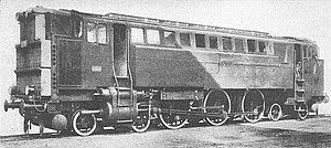
DR V 120 001
| DR V 120 001 | |
|---|---|
| Numbering: | V 3201 from 1930: V 120 001 |
| Number: | 1 |
| Manufacturer: | Maschinenfabrik Esslingen , MAN |
| Year of construction (s): | 1927 (used from 1929) |
| Retirement: | 1933 |
| Axis formula : | 2'C2 ' |
| Length over buffers: | 15,800 mm |
| Total wheelbase: | 12,500 mm |
| Service mass: | 124.6 t |
| Wheel set mass : | 18 t |
| Top speed: | 80 km / h |
| Indexed performance : | 993 kW i (1,350 PS i ) |
| Short term output: | 883 kW (1,200 hp) |
| Continuous output : | 735.5 kW (1,000 PS) |
| Starting tractive effort: | 110 kN |
| Coupling wheel diameter: | 1,600 mm |
| Impeller diameter: | 850 mm |
| Motor type: | 6-cylinder diesel engine |
| Power transmission: | pneumatic |
The V 120 001 was a diesel locomotive of the Deutsche Reichsbahn with pneumatic power transmission.
history
In 1924, the DR placed an order for the development of a powerful diesel locomotive for passenger train service on main and branch lines. Since the electrical or hydraulic power transmission that is common today was not yet developed, the problem of power transmission between the engine and wheels, which is crucial for large diesel locomotives, was solved via a pneumatic system.
A size and type basis for development was the class 78 steam locomotive , from which the performance data and the engine configuration were adopted. Test drives led to several changes, so that the locomotive built in 1927 and initially designated as the V 3201 was not put into service until 1929. It was assigned to the Reichsbahndirektion Stuttgart and in 1930 it was redrawn as V 120 001 (corresponding to the short engine power of 1200 hp).
The locomotive did not prove itself and was taken out of service in 1933. The V 140 001 with hydraulic power transmission was developed in its place .
Drive configuration
A 6-cylinder diesel engine from MAN in the design common in submarine construction and with a displacement of 400,789 cm 3 drove a two-stage compressor with which air was compressed to 6.5 atm (6.6 bar). If the motor was overloaded, 7 atm (7.1 bar) were also possible. The compressed air was heated by the engine exhaust gases in a heat exchanger to 350 ° C in order to supply the energy that was lost as heat during compression - this loss of heat is a fundamental disadvantage of pneumatic power transmission.
This compressed air was fed to a power unit as it was used for steam locomotives: two cylinders with a diameter of 700 mm worked with a drive rod on the middle of three coupled axles ; the controls corresponded to the Heusinger type.
The structure of the locomotive was box-shaped with two end driver's cabs, each of which had a large radiator for the engine on each end .
Performance data
The mathematical efficiency of the drive was 26%, the effective continuous power 1000 HP (735.5 kW) at 400 min −1 . For a short time, the power could be increased by increasing the engine speed by 50 min −1 to 1200 HP (883 kW).
literature
- Weisbrod, Bäzold, Obermayer: The great type book of German locomotives . Transpress Verlag ISBN 3-344-70751-5
- Isaac Franco, P. Labryn: Internal-Combustion Locomotives and Motor Coaches . Jumper. Dordrecht. 1931. ISBN 9789401761550 . P. 75 ff.
- Wolfgang Glatte: German Locomotive Archive: Diesel Locomotives. Transpress Verlag ISBN 3344707671
