
Roof capacity


As roof capacity is referred to an extended metal structure, on top of a radiating transmitting mast is mounted. Since the roof capacity extends the transmission mast electrically , the transmission mast can be built lower than would be necessary for a ground plane antenna .
At the top of a vertical antenna , which can not reach the necessary length λ / 4 due to the size of the wavelength to be emitted , horizontal wires or wire nets are stretched, which act like a capacitance to earth and thus electrically extend the radiator. So that the opposite pole of the λ / 4 radiator has low electrical resistance, either an earth network of (mostly radially arranged) wires is buried in the earth around the antenna base or a wire structure is arranged above the earth as a so-called counterweight . This is the only way to radiate as much of the HF energy as possible and not heat the ground.
The height of the antenna is electrically extended by a value by a suitable choice of the roof capacity


- ,

and additionally adjusted to resonance with the help of an extension coil at the lower end . The antenna current is distributed almost uniformly along the antenna height and is increased by the proportion of the capacitor current compared to an antenna without roof capacity . This results in a radiation resistance that is up to four times greater than that of a short vertical antenna without roof capacity.


The roof capacity does not contribute anything to the radiation of the electromagnetic wave. This is only done by the vertical wire indicated in the graphic as an antenna, the electrical cross-section of which is usually enlarged by several wires connected in parallel. Despite this measure, the shortened dipole is at a disadvantage in terms of efficiency compared to an antenna with a real antenna height of about λ / 4 .
A roof capacity of a special type was used for the transmission mast of the German station in Herzberg (Elster) . It consisted of an indoor walkable lens with a diameter of 25 m and a height of 4 m. A self-radiating transmission mast, 325 meters high and isolated from the ground, served as the antenna. To reduce earth losses, a total of 35 km of galvanized iron strips were laid radially around the antenna base. The facility was destroyed in World War II and later dismantled.

AFN antenna in Hirschlanden (Ditzingen)

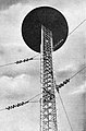
Spider web-like roof capacity at the top of the station Hirschlanden (Ditzingen)

Top of the Blosenberg tower with roof capacity
The lenticular roof capacity on the transmission mast of the Deutschlandender III

Roof capacity (horizontal rope field between the mast tips) of the transmitter systems in Mainflingen


See also
- Shortening capacitor , with the opposite effect
literature
- Jürgen Detlefsen, Uwe Siart: Basics of high frequency technology. 2nd edition, Oldenbourg Verlag, Munich Vienna 2006, ISBN 3-486-57866-9