Pull through
Pulling through is a manufacturing process and, according to DIN 8584, belongs to tensile compression forming .
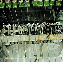
The most common application of this process is wire drawing . In this case, by a continuous casting and subsequent rolling output wire produced with typically about 8 mm in diameter through a die - also Ziehhol, die called a template or - put in more steps to the reduced Drahtenddurchmesser. When tool wire drawing lots the Ziehhol eliminated.
The manufacture of copper pipes is also usually carried out by several drawing processes following one another without intermediate treatment, the starting pipe being extrudedand recently it is increasingly being produced by continuous casting processes. When pulling pipes, a tool located in the pipe - called a plug or mandrel - is usually used in addition to the die, which determines the outside diameter, in order to achieve a defined wall thickness. In the case of long pipes that cannot be pulled straight, the internal tool is guided “on the fly”. The outer diameter of the inner tool is slightly larger than the die diameter. The inner tool gets stuck in front of the die during the drawing process and the pipe to be reduced in cross-section “flows” through between the die and the inner tool.
In the case of steel tubes and profiles made of steel and copper, on the other hand, drawing is primarily used for the final treatment to achieve high dimensional accuracy or a smooth surface. Copper profiles are often stretched beyond the yield point. This process, known as stretching, serves to straighten the workpiece. A desired solidification of the material also occurs.
The tensile force required for forming must be introduced on the outlet side of the drawn material strand. There are three basic designs of drawing machines:
- Drum drawing machines are used to process small material dimensions (wires, pipes with small diameters) with great lengths. The force is introduced via a drum around which the strand of material is wrapped after the die.
- Straight drawing benches are used for the production and processing of relatively short (up to about 30 m) or large cross-sections (profiles, pipes with large diameters). One or more workpieces of the same type are pulled through the die (s), the force being introduced at the beginning of the workpiece.
- Continuous drawing machines are basically suitable for a large length range of the workpieces. In practice, however, its use is mainly limited to pipes of medium and small diameter and medium length. The mode of operation of the continuous drawing machines is based on the fact that several clamping devices move the material to be drawn in such a way that at least one clamping device is always engaged. Widespread construction has two special backdrop rolls (also called cams) controlled clamping devices. Other designs have clamping jaws that are mounted on two chains that are mounted against each other and run synchronously .
The cross-sectional decrease in the drawing, and thus the diameter of the die must be so dimensioned to be that the tensile strength or the yield strength of the drawn material is not exceeded by the pulling force. Therefore, the drawing process usually takes place in several steps. When cold drawing steel and brass materials , soft annealing or patenting is required between the steps , whereas this is usually not necessary for copper materials.
literature
Rolf Hinkfoth: Solid forming: selected technological basics of the forming processes in metallurgy. Wissenschaftsverlag, Mainz; Aachen 2003, ISBN 3-86130-184-9

