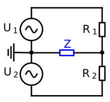
Galvanic coupling
A galvanic coupling (also called impedance coupling ) is a coupling in which the currents of two circuits flow over a common impedance Z. The currents each cause a voltage drop at the coupling impedance, which can have a disruptive effect and is therefore undesirable. This common impedance is often a common reference conductor, a common forward conductor or, on circuit boards, the common ground of different circuits. It can be an ohmic as well as an inductive or capacitive resistor. This resistance is strongly dependent on frequency. With ohmic impedances, the resistance increases with increasing frequency due to the skin effect . The coupling effect of inductances also increases with increasing frequency, whereas that of ideal capacitances decreases.
The term impedance coupling is more suitable than galvanic coupling for couplings via the impedance of a capacitor .
Application examples
example 1
The components on a circuit board are arranged as shown in the adjacent picture. The transmitter and receiver are connected to one another via signal lines. In addition, all components use the same reference conductor. The inductance of the reference conductor is 260 nH. S1 switches a current of 20 mA in 10 ns. The resulting voltage drop on the reference conductor is approximately calculated as follows:
Example 2
Typical lines on printed circuit boards generally have an inductance per unit length of 1 µH / m. Switching a load current leads to a current increase of 600 mA in 0.1 µs in the line to the load. The inductive voltage drop on the line of 10 cm length on the circuit board is then approximately calculated as:
remedy
In order to prevent the galvanic coupling of circuits, a consistent potential separation is carried out. There are various strategies for this. The potential separation can be achieved by relays , transformers or optocouplers . Furthermore, galvanic decoupling is also possible by using separate lines and connecting two or more meshes in just one point, the star point. If a star-shaped reference conductor system cannot be used, the impedance coupling can be reduced by a low-impedance design of the common conductors, i.e. the largest possible cross-sections to reduce the ohmic resistance and short cable lengths to reduce the line inductance. For this purpose, reference conductors are flat or meshed. These decoupling measures still allow inductive and capacitive residual couplings, which in turn can cause interference.
literature
- Adolf J. Schwab: Electromagnetic Compatibility . 4th edition. Springer, 1996, ISBN 3-540-60787-0 , pp. 21-23 .


