Gas flow monitor
A gas flow monitor (GS) is a component of a gas system that automatically and immediately interrupts the gas flow if the gas line is intentionally or accidentally damaged. The GS is one of the active safety measures.
Flow monitors are to be installed in new systems and in the event of major changes to old systems.
Gas flow monitors are not to be confused with flow safeguards.
function
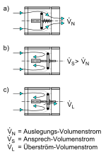
The gas flow monitor reacts to an additional volume flow that arises if the gas line is damaged by a higher flow rate than the design volume flow . This results in a pressure drop in the gas line downstream of the GS and thus a pressure difference on both sides of the GS. This moves the closing plate against a spring force into the valve seat and thus interrupts the gas supply to the following lines. If the closing plate has an overflow opening, the GS will open again automatically when the gas line is closed again and the gas pressure can slowly build up again. If this is not available, the GS must be opened manually.
When the line is started up, the gas should be let in slowly so that the gas flow monitor does not trip. A related sign on the main tap reminds of this.
Types
Gas flow monitors are identified with the letters K for plastic pipes and M for metal pipes .
Type GS K gas flow monitors may be used for plastic pipes and metal pipes. In lines made of multi-layer composite pipes , they are to be used in conjunction with a thermally triggered shut-off device (TAE). The combination is called GS-T K and is available from nominal size 1.6. The type GS M may only be used for metal pipes. It is available from nominal size 2.5. Other sizes are 4 and 6.
Installation locations
Gas flow monitors are to be installed directly behind the main shut-off device or the gas pressure regulator . If the pressure regulator is not located directly behind the main shut-off device, the GS can also be used in front of the pressure regulator at a line pressure of up to 100 hPa. Flow monitors can also be provided in front of the individual gas meters or the branches of the pipeline system.
No two flow monitors of the same nominal value and type should be provided along the flow path, as this would reduce the protected line length. (However, a GS K may be installed after a GS M integrated in a gas pressure regulator.)
With a total load of more than 138 kW or a single supply line with a nominal load of more than 110 kW, no gas flow monitors are required. Multi-layer composite pipe cannot be used in these cases.
interpretation
Flow monitors must be designed in such a way that the response volume flow is higher than the design throughput (maximum throughput) of each individual device connection.
Flow monitors are used in front of the house connection if the supply pressure is more than p> 100 mbar.
The selection can be made using Table L.0 of the TRGI . The design is based on the total load (total load) and not according to the reduced peak load.
Web links
- Gas flow monitor for gas installation - Sentry GS , Technische Literatur, Mertik Maxitrol


