DC braking

When DC braking is referred to in the drive systems , a brake method in which three-phase motors by means of direct current be braked. So that braking can take place using direct current, the stator winding must be disconnected from the mains and connected to a direct voltage source. Since the braking effect of DC braking decreases sharply shortly before standstill, the braking process must be stopped with a mechanical brake until it comes to a standstill.
function
When the stator is connected to the DC voltage source, a direct current flows in the winding . This direct current builds up a magnetic direct field. This constant field induces a voltage in the rotor rotating in it . Since the rotor winding is short-circuited, a current is made to flow in it. Due to the low resistance of the rotor, even small induced voltages are sufficient to generate a high current in the rotor. This current creates a magnetic field in the rotor . This magnetic field exerts a force on the current-carrying conductors of the rotor which, according to Lenz's rule , is directed in such a way that the rotor is braked. As a result, the speed of the motor now drops. At the same time as the speed drops, so does the frequency of the voltage induced in the rotor and thus also the inductive reactance of the rotor. As a result, the ohmic resistance of the rotor now predominates . Due to the now predominant ohmic resistance, the braking effect increases with decreasing speed. The braking torque in DC coast-down braking only drops sharply shortly before standstill and decreases to zero when the rotor is at a standstill. In contrast to countercurrent braking , the motor cannot run up in the opposite direction after standstill .
circuit
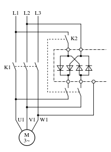
With DC braking it is necessary that two or three phases of the stator winding connected in series are fed with direct current. The best braking effect is achieved when the stator winding is connected either in a star or in a delta. The DC voltage is then connected to two connections on the stator winding. With the star connection, either the open or the closed star connection can be used. With the open star connection, one line remains unused; with the closed star connection, two lines are connected. A transformer is used to generate the DC voltage , the AC voltage of which is rectified via a bridge rectifier. So that the DC voltage can be switched to the stator winding, the supply voltage of the motor must first be switched off. The level of the voltage is monitored by a special voltage relay so that the rectifier cannot be destroyed by alternating voltages generated by the stator winding when switching from alternating to direct voltage. So that the windings are not excessively heated by the direct current, the direct voltage source is switched off again when the braking process has ended.
DC voltage level
Since only the ohmic resistance of the stator windings is effective for the direct current, the level of the direct voltage used must be considerably below the rms value of the rated motor voltage. The DC voltage can be approximately ten to fifteen percent of the nominal AC voltage. However, the level of the required DC voltage depends not only on the rated voltage of the motor, but also on the rated motor power. For motors with a high rated motor power, lower voltage values are required for the same rated motor voltage than for motors with a low rated motor power. For an average braking torque that roughly corresponds to the rated motor torque, a direct current is required that is roughly 2.5 times the rated motor current.
application
DC braking can be used with slip-ring motors and three-phase motors with squirrel cage rotors . With slip-ring motors, the braking torque assigned to the speed can be influenced by means of rotor resistors . The centrifugal mass energy of the machine and the electrical power supplied to the stator are converted into heat in the rotor. This causes the motor to heat up when braking. For this reason, this braking method is not suitable for braking large centrifugal masses. This method is not suitable for periodic braking either.
literature
- Detlev Roseburg: Electrical machines and drives. Fachbuchverlag Leipzig in Carl Hanser Verlag, 1999, ISBN 3-446-21004-0
Individual evidence
- ^ A b c Ralf Kories, Heinz Schmidt-Walter: Taschenbuch der Elektrotechnik. 8th expanded edition, Verlag Harry Deutsch, Frankfurt am Main 2008, ISBN 978-3-8171-1830-4 .
- ↑ a b c d e f Günter Boy, Horst Flachmann, Otto Mai: The master's examination in electrical machines and control technology. 4th edition, Vogel Buchverlag, Würzburg, 1983, ISBN 3-8023-0725-9 .
- ↑ a b c Georg Flegel, Karl Birnstiel, Wolfgang Nerreter: Electrical engineering for mechanical engineering and mechatronics . Carl Hanser Verlag, Munich 2009, ISBN 978-3-446-41906-3 .
- ↑ a b Ernst Hörnemann, Heinrich Hübscher: Electrical engineering specialist training in industrial electronics. 1st edition. Westermann Schulbuchverlag GmbH, Braunschweig, 1998, ISBN 3-14-221730-4 .
- ↑ a b c d e Helmut Greiner: Starting, braking, positioning with three-phase asynchronous motors. Danfoss Bauer GmbH, Esslingen 2001 Online (accessed March 8, 2012; PDF; 9.1 MB).
- ↑ Germar Müller, Bernd Ponick: Basics of electrical machines. 9th edition, Wiley-VCH Verlag GmbH & Co KGaA., Weinheim 2006, ISBN 3-527-40524-0 .
- ↑ Manfred Rudolph, Ulrich Wagner: Energy application technology. Springer Verlag, Berlin Heidelberg 2008, ISBN 978-3-540-79021-1 .

