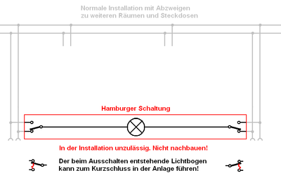
Hamburg circuit
The Hamburg circuit ( English Carter system ) is a special form of the economy changeover circuit in electrical installations. She is in Germany to DIN VDE 0100 -460 section 465.1.2 and DIN VDE 0100-550, section 5 and in the United States after the National Electrical Code (currently NEC Article 404.2) since 1923 in newly installed or in old and advanced low-voltage systems not permissible because the neutral conductor must not be switched single-pole (VDE 0100-460).
The risk of Hamburger circuit is that it is switched off at lights with missing shock protection (older design) may bear the potential of the outer conductor at the lamp thread, and that even when the lamp is turned off and therefore the layman be apparent "de-energized" should. This is because with the Hamburg circuit a state can be achieved in which the voltage of the outer conductor is applied to both poles of the lamp socket.
As a result, a person can suffer an electrical accident if they touch the lamp thread (e.g. when changing a light bulb) .
In addition, unsuitable changeover switches can cause a short circuit between the outer conductor and the neutral conductor : The arc that occurs when switching off is initially in series with the consumer, as is the case with other installation circuits , but is triggered directly by the switching element at the end of the switching process if it has not been extinguished by then commutated to the outer and neutral conductor.
Hamburg circuits in old systems (built before May 1973) are still under protection if they were built according to the standards valid at the time of construction and if no changes are made to them. This particularly applies to the replacement of the previously used rotary switches suitable for the Hamburg circuit with new rocker switches. Nevertheless, some toggle switches are now labeled with N and L.
Structure and use
The hamburger circuit was used to
- to enable a changeover circuit with a single conductor per switching point to the luminaire, starting from positions where the neutral conductor and outer conductor were already available.
- To be able to lay cables with fewer wires (e.g. a NYM 4 × 1.5 mm² instead of a NYM 5 × 1.5 mm²).
- Cables that contain too few cores can still be used for a two-way circuit.
The specialty (and danger) of the circuit is that the lamp is in the only corresponding one. (Corresponding is the designation of the connection line (s) between two changeover switches.)
With only a four-wire connection between two changeover switches, additional sockets could be attached to both switches. In this case, the required conductors were the only corresponding ones, the outer conductor , the neutral conductor and the protective conductor . The second corresponding, which is necessary with a conventional two-way circuit, could be saved.
Types of two-way circuits
- Changeover
- Economy changeover
- Hamburg circuit
literature
- Alfred Hösl, Roland Ayx, Hans Werner Busch: The electrical installation in accordance with regulations, residential construction, commercial industry. 18th edition, Hüthig Verlag, Heidelberg, 2003, ISBN 3-7785-2909-9
Individual evidence
- ↑ Reinhard Opitz: Current standards and transitional provisions from DIN VDE. (PDF; 1.4 MB) (No longer available online.) ABB, p. 19 , archived from the original on January 6, 2012 ; Retrieved April 13, 2012 .
- ↑ Requirements for lighting circuits in multi-party residential complexes. (No longer available online.) Elektrofachkraft.de, archived from the original on December 28, 2011 ; Retrieved April 13, 2012 .
- ↑ Switching a neutral is generally forbidden by the NEC unless the hot conductor is opened simultaneously. See NEC Article 404.2 Switch Connections: (A) ... Three-way and four-way switches shall be wired so that all switching is done only in the ungrounded circuit conductor ... (B) Grounded Conductors. Switches or circuit breakers shall not disconnect the grounded conductor of a circuit. Which is why it is expressly forbidden to single-pole switch the earthed neutral conductor!
- ↑ The requirement from DIN VDE 0100-550 Section 5 was taken over from VDE 0100: 1973-05 §31 b) 3. Statement: "For changeover switching with single-pole changeover switches (switch 6, VDE 0632, table IV) the center conductor or a second outer conductor must not be used."
