
Industrial computed tomography

The industrial computed tomography (ICT) - here more precisely X-ray computed tomography - (abbreviated: CT) shows some essential differences compared to the medical CT, which is mainly dealt with in the article computed tomography . In the medical field, the object to be examined (the human being ) is of relatively uniform size (approx. 1.5 to 2.0 m) and composition (approx. 63% water , few heavy elements ). This is not the case in the industrial sector. Objects from a few millimeters to many meters as well as homogeneous (e.g. pure metals) and completely inhomogeneous components (e.g. fiber composite materials ) must be examined and displayed in three dimensions. Therefore, the requirements for industrial CT systems, as well as their designs, are sometimes significantly different and more diverse than medical CT systems.
Industrial CT can be classified in different ways depending on the criteria applied. Classifications according to the geometry of the recording system or according to the details of the systems are common.
functionality
A special feature in which the industrial CT differs from the medical one lies in the often different recording geometry compared to medical systems. There the patient usually lies cooperatively and motionless, with the X-ray source (s) and detector (s) moving around him, coupled to one another. In the industrial sector, where only inanimate objects have to be examined, the X-ray source and detector can be firmly positioned and only the examination object rotated, which is mechanically easier.
Process of an industrial computed tomography
When using industrial computed tomography, the preparation of the metrological evaluation and measurement of the test items can be started before the components are manufactured. The CAD data used by the development department to design the component are used to create the ICT test plan by determining the reference and alignment points of the component and defining the individual measuring points. As soon as the first near-series component is completed, it is scanned in the ICT system, converted into 3D volume data and read into an evaluation software. The 3D model of the scanned component is then aligned with the CAD design data using the software and the measurement is carried out using the test plan that has already been created. The measurement deviations are shown in a log, displayed in color according to their degree of deviation and statistically evaluated if required.
Illustration of the complete inner workings of a component
With the ICT analysis, the user can see the complete inner and outer geometry of his workpiece in all details. The smallest deviations and component defects are precisely localized. The bandwidth of the evaluations ranges from wall thickness and porosity analyzes, the defect and assembly control to the checking of properties that are not possible with conventional measuring methods . Soft materials such as elastomers or rubber parts can now also be precisely determined using measurement technology. Due to the recording and measurement of the undestroyed test item, the ICT is also used to record the volume of air pockets, bores or liquids.
Finite element calculation possible via reverse engineering
The tomographic measurement of the component also offers a further advantage. With the resulting data, a finite element calculation can be carried out on the "real" component for the first time using reverse engineering . This means that the resulting ICT data of the real component is converted into CAD data and the weak points are then determined via the FEM. Up to now, this was only possible with the CAD data that was designed and created free of process-related errors .
Classification according to the geometry of the recording system
Two-dimensional CT

A single slice of the object is examined and reconstructed. This is done through all-round irradiation and detection of the X-rays with a line detector. The X-ray source sends out a fan beam. The layer structure of the object is numerically reconstructed using the recorded X-ray projections.
Advantages:
- High resolution of details
- Little interference from scattered radiation
Disadvantage:
- Long measurement times for volume measurements
- It must be possible to see through the object from all sides
This method is mainly used for:
- Dimensional accuracy tests
- Error checking
- Dimensional measurement
Three-dimensional CT

Here the entire volume of an object is examined by irradiating it from all sides. The X-ray source emits a cone beam, which is detected with a flat panel detector.
Advantages:
- Direct generation of a volume model
- Short measuring times (down to 25 s for a volume)
- Automatic volume data evaluation possible
Disadvantage:
- The object must be penetrable from all sides
- Technically complex and therefore expensive
- Reduced data quality due to scattered radiation
Applications for
- Visualization and dimensioning of internal structures
- 3D distribution of material properties (e.g. density , porosity )
- Error checking
Helix CT

This procedure is very similar to the method mainly used in medicine today, only here again with the difference that the X-ray source and detector stand still and the test object moves. Here, however, not only in one plane, but with simultaneous movement in the longitudinal direction, which overall means a helical movement when viewed from the object .
Advantages:
- Examination of objects of any length
- Reduction of artifacts (Feldkamp algorithm )
Disadvantage:
- Mechanically more complex (due to the additional movement axis)
Areas of application:
- measuring technology
- Examination of long objects
Laminography / Tomosynthesis

This is where the layer-by-layer examination and reconstruction of mainly flat objects take place, which may not be accessible from all sides. The procedure can in turn be divided into:
- Translational laminography: Here the object is pushed between the X-ray source and detector. Due to the lateral offset, the interior can be reconstructed in three dimensions.
- Standard rotary laminography: Here the X-ray source and / or detector rotate above and below the object. The object can be reconstructed three-dimensionally using the information obtained from the different angles of incidence.
- High Resolution Computed Laminography (HRCL): HRCL is a special form of rotary laminography. In HRCL, the sample is rotated, not the X-ray source / detector structure. On the other hand, the alignment of the detector to the X-ray source can be changed. This enables the smallest sub-areas of large-area objects to be examined with high resolution (<1.5 µm / voxel real resolution). The HRCL is therefore particularly suitable for the non-destructive analysis of individual assemblies / soldered connections on electronic circuit carriers without laboriously preparing them.

Laminography has the following advantages:
- Generation of depth information without access from all sides
- Possibility of a section CT
Disadvantage:
- The depth information obtained is of limited precision
Laminographic processes are often used for:
- Testing of panel materials
- Testing electronic flat modules
- The investigation of large, flat components without access from all sides.
Classification according to size

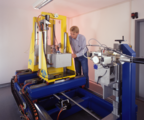
A typical macro CT system; on the right the image of the two x-ray tubes used in it with 450 kV (large cylinder) and 225 kV (small cylinder) acceleration voltage.
A sub-micro-CT system. The tube on the right, the detector on the left. Very close to the tube and very small the test object on a needle point on a turntable.
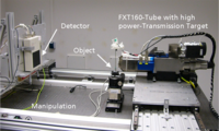
Construction of a micro-CT system; the X-ray tube in the foreground, the object on a turntable in the middle, the flat panel detector in the back


It is also possible to categorize recording systems according to the size of the objects to be examined or the ability to recognize details:
Macro CT
This is about the investigation of large objects (meter range). For this purpose, so-called X-ray sources with macro focus are used, which achieve details in the millimeter range. Such systems are often used to examine cast parts ( engine blocks , cylinder heads , etc.), but also for ceramics .
Micro-CT
These systems work with microfocus tubes that allow details in the micrometer range to be recognized. The available tubes, as well as requirements for sensible recording times, limit the object size to about 20 cm. Areas of application are plastic parts , metal parts made of light materials (e.g. aluminum) and also ceramic parts of suitable size.
Sub-micro-CT or nano-CT
Such systems achieve the highest resolutions of conventional CT devices. Special X-ray sources that have very small focal spots are used here. In addition, detectors with high resolution are used and work is carried out under high geometric magnification. This means that details can be recognized down to about 500 nm. With these orders of magnitude, however, the object size is limited to a few millimeters. Such systems are therefore often used in material characterization, for the highly precise examination of electronic components, or for biological samples (e.g. insects , plant seeds , etc.).
In addition, there are also classifications according to stationary or mobile, according to area of application (error detection, measuring technology) or according to the X-ray energy used (more energy method).
Exemplary fields of application of ICT
In addition to the expanded engineering options, industrial computed tomography can provide time and cost advantages for a wide range of products. The technology is ideal for analyzing workpieces with complex internal geometries as well as components made of different materials. The areas of application include:
- all supply areas for the automotive industry
- the plastics and electronics industries
- Determination of the fiber orientation in plastic components for the validation of simulations
- Parts produced by casting
- Measurement of assembled or assembled assemblies
- Digitization of drill cores for subsequent simulation of the flow properties ("Digital Rock")
Examples

Results of an industrial 3D-CT; on the left the photograph of the examination object (steering housing made of cast aluminum), on the right the CT image showing pores and inclusions (in red)

Pinecone. Shown with "CT Alpha" from Procon X-Ray. Seeds in red.
Flight through a stack of CT images in the Z (height) direction. The earplug shown is inserted into a simulated styrofoam ear canal and adapts to its shape.

Disposable salt mill with plastic grinder in a Helix-CT
Flight through a 3D reconstruction of a Helix CT on a disposable pepper mill


literature
For mathematical reconstruction:
- T. Buzug: Introduction to Computed Tomography . Springer, 2005, ISBN 978-3-540-20808-2 , CT in the medical field
- WA calendar, computed tomography. Fundamentals, device technology, image quality, applications , Publicis Corporate Publishing, 2006, ISBN 978-3-89578-215-2 , Industrial CT
- Berichtsband International Symposium on Computed Tomography and Image Processing for Industrial Radiology . Berlin 2003, ISBN 3-931381-48-X
- Berichtsband International Symposium on NDT in Aerospace . Berlin 2008, ISBN 978-3-940283-12-2
- Magazine NDT & E . Elsevier, ISSN 0963-8695
- MP Materials Testing magazine . Hanser, ISSN 0025-5300
Standards and guidelines
Standards and guidelines with direct reference to industrial X-ray computed tomography for coordinate measurements are:
- DIN EN 16016-1: 2011 Non-destructive testing - Radiographic methods - Computed tomography - Part 1: Terminology
- DIN EN 16016-2: 2011 Non-destructive testing - Radiographic methods - Computed tomography - Part 2: Fundamentals, devices and samples
- DIN EN 16016-3: 2011 Non-destructive testing - Radiographic methods - Computed tomography - Part 3: Implementation and evaluation
- DIN EN 16016-4: 2011 Non-destructive testing - Radiographic methods - Computed tomography - Part 4: Qualification
- VDI / VDE 2617 sheet 13: 2011 Accuracy of coordinate measuring machines - parameters and their testing - guidelines for the application of DIN EN ISO 10360 for coordinate measuring machines with CT sensors
- VDI / VDE 2630 sheet 1.1: 2009 Computed tomography in dimensional measurement technology - basics and definitions
- VDI / VDE 2630 sheet 1.2: 2010 Computed tomography in dimensional measurement technology - influencing variables on the measurement result and recommendations for dimensional computed tomography measurements
- VDI / VDE 2630 sheet 1.4: 2010 Computed tomography in dimensional measurement technology - comparison of different dimensional measurement methods
- VDI / VDE 2630 sheet 2.1: 2013 Computed tomography in dimensional measurement technology - determination of the measurement uncertainty and the test process suitability of coordinate measuring machines with CT sensors
Web links
Individual evidence
- ↑ G. Lautenschläger: Areas of application of High Resolution Computed Laminography (HRCL). Fraunhofer IKTS, July 14, 2017, accessed on August 9, 2017 .