I-link
As I-member is referred to a LZI - transmission member in the control engineering , which has an integrated transmission behavior. That is, the rate of change of the output variable is determined by the input variable.
The associated functional relationship in the time domain is
- or also ,
so that the complex transfer function in the image area takes the form
Has. Here, K, K> 0, denotes the transmission constant or the gain factor of the I element, or T I the integration time.
If the I-element is used as part of a PID controller, it is responsible for the regulation, i.e. i.e., it has no permanent control deviation. The I element can, however, also be part of the controlled system, for example with speed as the input variable and position as the output variable. In this case, the controller concept must provide for the reversal of the integration (normally using a D element).
Bode diagram
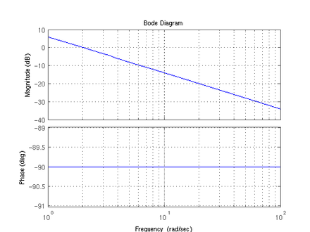
The I link is . Therefore, the following applies to the amplitude and phase response in the Bode diagram :
The amount characteristic is thus a straight line that falls at 20 dB / decade and has the value K dB at ω = 1 . The phase characteristic is constant −90 °.
Step response
The step response of the I-element describes a straight line with the gradient .
Locus
The locus ( ) of the I-element runs for K> 0 on the imaginary axis, coming from at and ending at the zero point for .


