Coupling switch

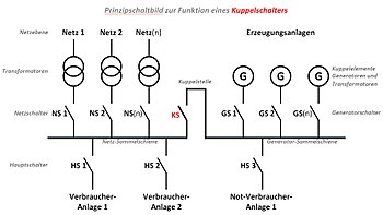
A coupling switch (KS, also coupling switch , partly also transfer switch ) is in electrical energy technology a switch that is often remotely operated and used to switch a system-relevant energy generation or energy consumption system on and off .
function
The coupling switch differs from other electrical switches in that it connects system-relevant, particularly important system parts. If the coupling switch is intrinsically safe, the respective switching status is monitored and for particularly important and reliably functioning isolating and switching functions, two coupling switches are used in series (redundant structure).
Each coupling switch must have at least one load switching capacity that corresponds to the nominal power of the electrical system to be coupled or disconnected . These can contactors , motor protection switches or mechanical performance or load break switches are used. If there are special protection requirements associated with switching, the coupling switch may have to be able to switch the short-circuit power (e.g. if there is a fault and high overload currents or short-circuit currents have to be switched).
Automatic coupling points usually do not protect the system against overload and short circuits. The extent to which a mechanical overlap should occur between the normally open and normally closed contacts when the coupling switch is switched is determined by the respective application.
Coupling point / uncoupling point
The coupling point or decoupling point refers to the point in the supply network at which the coupling / decoupling into or from the network takes place. This point can, but does not have to be, the generator switch (GS) or a mains circuit breaker (NS).
Examples
Central network and system protection
A central network and system protection (NA protection, decoupling protection) consists of two essential components:
- Grid and system protection relay that monitors the power grid, and
- one or two tie switches.
It can be an in-house construction or z. For example, according to VDE 4105 for renewable energy generation systems, a “type-tested protective device with proof of conformity”, which constantly monitors the voltage and frequency of the supply network for compliance with the specified tolerances, and disconnects or connects the system on all poles from the supply network in the event of a specified deviation.
ENS
A device for network monitoring with assigned switching devices (ENS) works in a similar way to NA protection and is approved in Germany and Austria for small power generation systems with a maximum output of 30 kW . This is to prevent islanding and the resulting feed back into the power supply network, because this could possibly lead to dangerous effects.
The KACO company z. For example, with Powador-protect, a control of internal coupling switches for several KACO inverters and also external coupling switches has been developed, which combines the entire shutdown chain for NA protection / coupling switch (decoupling protection) and makes it fail-safe and offers an additional level of security.
swell
- ↑ Generation or consumption of energy is basically not possible, only conversion. In the following, however, the colloquial and undifferentiated use of the words generation and consumption in connection with energy conversion is used.
- ↑ This protection is different, in Germany z. B. in accordance with VDE 0100-712, VDE 0100-430 or VDE 0100-530.
- ↑ E.g. photovoltaics , combined heat and power plants and biogas or wind power plants .
- ↑ In the TN-C network and TN-C part of a TN-CS network , only the three phases may be switched. In the other network types, the neutral conductor may also have to be switched. Switching or disconnecting the PE or PEN conductor is generally not permitted.
- ↑ The VDE-AR-N 4105 in chapter 6.1 requires the use of a central NA protection for photovoltaic systems over 30kVA (inverter) system output. In Austria: TOR part D.4, points 5 and 6 in conjunction with ÖVE / ÖNORM E 8001-4-712.
- ↑ The equipment monitors its function independently and switches off automatically when an (internal) error is detected or prevents it from being switched on again (VDE-AR-N 4105 A.6).
