
LIV characterization
The LIV characterization is an optical-electrical measurement technology of laser diodes . The designation LIV is derived from the common English symbols for these parameters, where L stands for light, I for electrical current and V for electrical voltage .
The technology is used in the development and manufacture of laser diodes in order to measure the characteristic curves . These are the optical power and the voltage drop across the diode depending on the current flow through the diode. From the results of a LIV measurement, the development or production engineer receives information that provides information about the quality of the diode, i.e. whether the diode is OK or rejected.
Areas of application
In the event that the goods are OK, the LIV measurement data are usually archived and delivered as a test report with the laser. Accordingly, there are different phases of laser production in which a LIV measurement makes sense. A representation of the work steps in the production of high-power diode lasers (HPDL) can be seen in the following figure.

The first way to measure the performance of the laser chips is after the wafers have been cut into bars and the end facets have been coated. At this point, LIV curves are recorded in order to sort out defective laser chips before final assembly. This saves time and money in the manufacture of the end product, since the further steps are very complex and expensive. At the end of the process chain before and after the "burn-ins" , the laser diodes are characterized again with an LIV test system.
According to the different properties of the lasers in these two production stages, different conditions are used for the LIV measurement. While the lasers are still in the form of bare chips or bars, they do not yet have any suitable means of emitting operating heat. The laser must therefore be energized in very short pulses in order to avoid improper thermal stress on the laser. This requirement usually means that the current pulses must have a duration of a few microseconds to less than 1 µs. In order to get accurate measurement results and to avoid incorrect loading of the laser diodes, these current pulses have to be clean, rectangular and without overshoots.

At the end of the production chain, the laser chips (or bars) are mounted on heat sinks with good thermal conductivity. In this state, the LIV test can be carried out with long pulses (QCW = quasi continuous wave ) or continuous current (CW = continuous wave ).
Measuring process
The process for measuring the LIV characteristics of a laser diode consists of energizing the laser with increasing current and measuring the optical power of the laser and the voltage drop across the laser as a function of the current. Depending on whether a chip (or bar) or a fully assembled laser is measured, the current can be conducted in pulsed or permanent (CW) form.

Each time the current is set, the optical power from the laser and the voltage across the laser are measured and stored. At the end of the measurement, these values are displayed in graphs (characteristic curves) and evaluated. Examples of these characteristics are shown here.
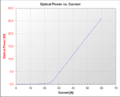
Optical performance as a function of current

Voltage as a function of current


Device technology
From the description of the measurement process it can be seen that the measurement requires a synchronized recording of measured values. The following remote controllable or communicating devices are therefore required:
- controllable power source
- optical power meter
- Current and voltage measuring devices
- possibly spectrometer
In most cases, a thermostated heat sink or thermostat is required, since the characteristic values are temperature-dependent. Since the data must be saved and the parameters controlled, an interface for PC operation is very useful. There are suppliers of different devices for these different measuring tasks. Some providers also specialize in this area and offer integrated systems that combine the various hardware components in a few or in one device.
evaluation
From these characteristics it can be seen that the measured laser is working properly. The optical power is minimal up to a certain current, called the threshold current . The optical power increases sharply above the threshold current. This increase is usually very linear. Accordingly, it is common to characterize this characteristic with two parameters: the threshold current and the increase in power per ampere of additional current in the linear range - the so-called "slope efficiency". The laser can be assessed as good or bad on the basis of these two parameters. In addition, the performance curve should not bend at the upper end or otherwise show noticeable changes in gradient in the linear range (so-called " kinks "). A kink in the power curve is an indication of excessive thermal stress on the laser. "Kinks", on the other hand, indicate defects in the crystal structure and can predict premature failure of the laser. The easiest way to identify these two defective properties is to consider the first derivative of the optical power as a function of the current.


The voltage curve should start at a certain value ( open circuit voltage ) and increase steadily but not linearly with the current. The serial resistance of the laser can be derived from the last - almost straight - portion of the voltage curve .

In addition to recording the measurement data for power, current and voltage, it can be useful to measure the optical spectrum at the same time. This is possible with suitable hardware and saves valuable testing time.
Individual evidence
- ↑ Steve Wright, Bernhard Neumann: LIV measurement technology for laser diode characterization: quick and easy . In: Photonics . No. 5 , 2013, p. 30–33 ( PDF [accessed October 26, 2013]).
- ↑ (PDF; 1.9 MB) . Agilent Technologies, accessed October 26, 2013.
- ↑ Lawrence A. Johnson: Laser Diode Burn-in and Reliability Testing (PDF; 2675 kB). Retrieved October 26, 2013.
- ↑ https://www.cmc.ca/en/WhatWeOffer/Products/CMC-00025-20067.aspx
- ↑ https://download.tek.com/manual/2520-903-01_B_Mar_2003_0.pdf
- ↑ https://www.artifex-engineering.com/index.php/de/instruments-4/systeme-zur-charakterisierung-von-laserdioden