Network simulation
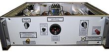
A network simulation ( Line Impedance Stabilization Network , abbreviated LISN or also Artificial Mains Network , abbreviated AMN ) is an electrotechnical device that is used to measure the line-bound interference emission as part of measurements and tests for electromagnetic compatibility (EMC) as a simulation of supply networks becomes. This may be the low-voltage network , a board network (eg. As in a car or plane) or a tele communications network to be. In an EMC test, part of an overall test is used to determine which radio interference voltages are emitted by the device under test (test item) to the supply network. If the radio interference voltages of the device under test are above the permissible limit values, this must be suppressed, see radio interference suppression .
A network simulation has the following tasks:
- Suppression of any high-frequency interference from the supply network.
- Provision of a standardized impedance on the mains voltage side for the device to be tested.
- Decoupling of the high-frequency radio interference voltage from the device under test, which is superimposed on the mains voltage supplying the device under test, so that it can be fed to a measuring receiver or spectrum analyzer for further processing . It thus represents a defined connection between the test object, the supply network and the measuring device. Spectrum analyzers or measuring receivers , which are special receiving devices for high-frequency signals, are usually used as measuring devices for radio interference voltage .
Since there are very many different supply networks, the number of variants among the network simulations is correspondingly large.
The typical frequency range for radio interference voltage measurement is between 9 kHz and 30 MHz for low-voltage and telecommunications networks and between 150 kHz and 108 MHz for vehicle electrical systems, e.g. B. in motor vehicles.
In the subsequent higher frequency ranges, the field-bound interference emission is usually measured with antennas .
The network simulation should not be confused with coupling / decoupling networks ( CDN for Coupling / Decoupling Network ), which are used for the line-based coupling of narrow-band, high-frequency interference to the test object. These are used to test the immunity of the device under test against such narrow-band RF signals.
Norms
The specifications according to which network replicas must be built are set out in various standards and specifications. These include:
- CISPR 16-1-2: Specification for radio disturbance and immunity measuring apparatus and methods - Part 1-2: Radio disturbance and immunity measuring apparatus - Coupling devices for conducted disturbance measurements
- EN 55016-1-2: Requirements for devices and equipment as well as definition of the procedures for measuring high-frequency interference emission (radio interference) and interference immunity (identical to the international CISPR 16-1-2)
- VDE 0876-16-1-2: Implementation of EN 55016-1-2 into a DIN standard

