Buffer (train)
Buffers are pieces of equipment on rail vehicles that absorb pressure forces between individual vehicles. For the track terminations, some of which are also known as buffers, see buffer stop .
Layout and function
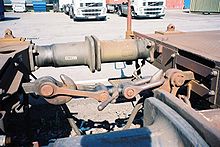
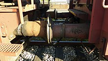
Buffers are the superstructures and attachments that carry the impact / impact surfaces (buffer plates) and also contain the built-in damping devices ( impact absorption elements ). They are mounted on the so-called buffer beam (→ buffer beam) on the front sides in such a way that they can absorb the impacts and compressive forces acting from outside in the longitudinal direction of the vehicle. There are paired page buffer arrangements or single center buffer arrangements. In the case of the latter, the connecting couplings are often attached in pairs on both sides of the central buffer for the symmetrical distribution of the forces , unless the central buffer itself is also provided with a coupling device.
Designs
In the 1830s, as with the Adler locomotive , wooden buffers were still used in some cases.
Rod buffer
The first rod buffers consisted of a rod that carried the buffer plate at one end. The buffer rod was movable backwards on a spiral evolute spring (clock spring ), which was supported by a strong sheet metal sleeve. Squeezing the spring dampened the shock. The first spring loaded buffers were invented by John Baillie in 1846.
Today, rod buffers can only be found on museum vehicles.
Sleeve buffer
Since the relatively thin buffer rods often bent during operation and caused major damage in the event of accidents, the sleeve buffer was developed. The buffer plate sits on a steel tube with a larger diameter, which is more resistant to bending.
The evolute spring system, which was initially still used for the sleeve buffers, had the disadvantage of completely releasing the energy that was put in when the buffers were compressed, so that the vehicles were pushed apart again after the impact. This required trains to be braked evenly and, above all, not only selectively, in order to avoid vibrations in the train formation , which u. a. can cause the couplings to break. An improvement was achieved through the use of ring springs , as these convert a large part of the energy introduced into frictional heat.
Central buffer couplings
In central buffer couplings, the tasks of buffers are usually transferred to the coupling elements, which are designed to be correspondingly stable and are mounted with interposed spring elements within the vehicle frame (instead of a buffer beam ).
Normalizations
In the early days of the railway, each railway company determined the location and arrangement of the pulling and pushing devices at its own discretion. After a network began to develop from independently built routes, this hindered the interchange between cars. Vehicles that were to be transferred to the network of other companies had to be equipped with several buffers or coupling systems. In the course of the development of the technical unit in the railway system , the usual dimensions for buffer level and spacing in England and Northern Germany were established as regular dimensions.
- For all vehicles built since January 1, 1939, the distance according to RIV §38 was set at 1750 mm ± 10 mm.
- The middle of the buffer of European railway vehicles may be between 940 and 1065 mm above the upper edge of the rail .
Spain was an exception for a long time. Because of the introduction of force into the longitudinal girders of the wagons, which are further out due to the broad gauge, a buffer distance of 1950 mm was set there. Transitional wagons were therefore given wider buffer plates. The adaptation to the international regularity took place until the 1990s. Extra-wide buffer plates are still common in Spain, and the French Corail cars were also equipped with them. The larger buffer distance is also common in the broad gauge networks of Portugal, India, Pakistan, Bangladesh and Sri Lanka, as well as Argentina. Due to the lower passage of Portuguese wagons into the standard gauge network, extra-wide buffer plates are less common in Portugal. Passenger cars for long-distance traffic were almost completely equipped with it. Locomotives and wagons with extra-wide Iberian buffers also reached Argentina through vehicle sales.
The European railway companies use standardized buffers:
- Freight car: buffer with 75 mm stroke UIC 526-2 VE 1981-01. However, these buffers are currently no longer in use.
- Freight wagons: Buffers with 105 mm stroke UIC 526-1 VE 1998-07
- Freight wagon: buffer with 130/150 mm stroke UIC 526-3 V 1998-07
- Bumpers for passenger coaches UIC 528 VE 1991-01
The aforementioned UIC leaflets were replaced by the EN 15551 standard following the introduction of the "Interoperability Guidelines" TSI.
shape
In many cases, the buffer on the left side in the direction of travel was designed with a flat plate, the right-hand side with a curved plate, so that a flat and a curved plate always meet and edge pressure is avoided.
According to the UIC regulations of 1961, all vehicles in Europe are equipped with buffer plates that are curved on both sides but are significantly flatter. The radius of the buffer curvature is 1500 mm for passenger coaches and 2750 mm for freight wagons built since 1994. Round buffer plates with a diameter of 340, 370, 450 or 500 mm are common for freight wagons. Rectangular plate shapes are generally used for passenger coaches and locomotives, with the edge facing the longitudinal center of the vehicle being beveled due to the space required by the coach junction. There are also buffer plates in different shapes and widths, with the height between the upper and lower horizontal edge between 340 and 360 mm. According to EN 15551, the standardized widths for freight wagon buffers are 450 or 550 mm, for Spain 550 or 650 mm with a height of 340 mm each. The buffer plate widths for passenger coaches are between 600 and 720 mm, depending on the vehicle geometry. Buffers with non-round buffer plates cannot be rotated in any case.
The remaining space between the vehicles is called the Bern area .
A British specialty are pull-out buffers on passenger coaches and locomotives with hinged central buffer couplings type Janney. If similar vehicles are connected using these central buffer couplings, the buffers are pushed in and ineffective. For coupling with vehicles that are only equipped with screw couplings, the buffers are pulled out and locked in this position with the locking pieces.
Trivia
Railway fans are also jokingly referred to as "puffer kissers" or "puffer kissers".
Web links
Individual evidence
- ↑ Buffer. In: Viktor von Röll (ed.): Encyclopedia of the Railway System . 2nd Edition. Volume 3: Braunschweigische Eisenbahnen – Eilgut . Urban & Schwarzenberg, Berlin / Vienna 1912, pp 138 -145.


