Self-holding function
In the case of a self-holding function or a self-holding circuit , a short switching command (e.g. pressing a button) triggers a permanent change of state. Such a function can often be found in electrical installations of systems and machines.
Latching circuits are traditionally implemented with relays or contactors ; in electronics they have their equivalent in the flip-flop . Self-locking is also possible with pneumatic and hydraulic circuits.
A common (but not mandatory) feature of the self-holding circuit is that the control circuit is separate from the working circuit. The control voltage can then also be a protective extra-low voltage . Direct voltage (6 V, 24 V, 100 V, 220 V) and alternating voltage (24 V, 42 V, 230 V) are common.
Self-holding circuit
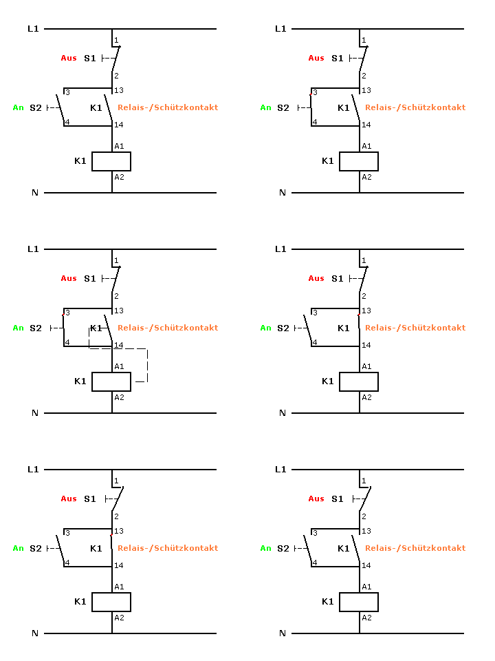
The latching circuit consists of a relay , two buttons and a contact (closer) of the relay. When the button S2 (closer) is pressed, the relay K1 picks up and closes the contact K1. If button S2 is released, contact K1 bridges it and the relay remains picked up. By pressing button S1 (NC contact) the relay is de-energized and drops out, K1 is open. If S2 is actuated, K1 would attract again and go into self-holding.
Depending on the position of the interrupting contact S1, a distinction is made between primarily setting and primarily resetting. If S1 is wired as shown in the figure on the right, it is said to be primarily resetting, since the relay would not pick up if S1 and S2 were operated at the same time. For a priority setting - i.e. in which the relay K1 picks up when S1 and S2 are operated simultaneously - S1 and the normally open contact of K1 must be connected in parallel with S2 in series.
application
The self-holding circuit is used in control circuits as an actuator with a memory function in which the switch, e.g. B. a motor contactor, after its activation by an external control pulse, keeps itself activated by the self-holding as long as the power supply exists. This means that, for safety reasons, it can also be used to reset itself to the inactive state after a power failure. So it prevents z. B. that a machine tool starts up again automatically when the machine power supply is automatically built up again after a power failure due to the return of the mains voltage . (An automatic start of motors after voltage recovery would pose a danger to the operator). The control circuit for activating a motor can also contain the switching contacts of protective and monitoring devices (e.g. door contact, motor protection switch , overtemperature switch , emergency stop button).
Increased security
For safety-related circuits in accordance with the Machinery Directive, there are so-called emergency stop switching devices (not to be confused with emergency stop buttons ). With duplicate contacts in series, these guarantee the safe shutdown of a machine in accordance with the required safety category . They contain, also through positively driven contacts, safe self-holding circuits for connecting emergency stop buttons, start buttons and limit switches (for example of protective doors) or light curtains . Sometimes they also contain the required contactors or load relays .
In order to be able to monitor the dropping out of the relays or contactors, they are designed with positively driven contacts: if a contact welds and does not open, all other normally open contacts remain closed and prevent reconnection, which is done via the normally closed contacts for this purpose .
Electronic embodiment
Today, self-holding functions are often implemented in programmable logic controllers (PLC) in software form. In addition to machines, this also applies to elevators , cranes and traffic lights .
The common SPS graphical programming language "LAD" (see Ko ntakt p lan ) includes switching symbols button (NC, NO), relay contacts and relay coils to the programming with the knowledge to facilitate an electrician.
The electronic equivalent of a self-holding circuit is the RS flip-flop .
See also
literature
- Fritz Tröster: Regulation and control technology for engineers. Volume 2 control technology, 4th edition, De Gruyter Verlag, Berlin 2015, ISBN 978-3-11-041728-9 .
Individual evidence
- ↑ Bernd Bode: punch card technology . Springer Fachmedien, 1968, ISBN 978-3-663-03040-9 , pp. 22 ( limited preview in Google Book Search [accessed October 9, 2019]).
Web links
- Basics of electromechanical controls (accessed on December 28, 2015)
- Automation and Drives - SCE (accessed December 28, 2015)
