Serial peripheral interface
The Serial Peripheral Interface ( SPI ) is a bus system developed in 1987 by Susan C. Hill et al., At the time at the semiconductor manufacturer Motorola (now NXP Semiconductors ), and represents a "loose" standard for a synchronous serial data bus ( synchronous Serial Port ) with which digital circuits can be connected to one another according to the master-slave principle .
A similar bus system called Microwire exists from National Semiconductor .
Basics
properties
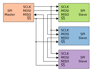
- The three common lines to which each participant is connected are:
- The data lines are sometimes also called SDO ( English Serial Data Out ) and SDI ( English Serial Data In ), whereby the designation is mostly made from the perspective of the respective bus participant, so that the lines must be cross-connected. Instead of connecting SDI with SDI and SDO with SDO, SDI must be connected with SDO of the remote station.
- One or more chip select lines with logic 0 active, which are all controlled by the master and of which one line is provided for each slave. Depending on the application, these lines are given different names such as SS , CS , STE or CE for Slave Select , Chip Select , Slave Transmit Enable or Chip Enabler , often in combination with an index number to distinguish them. There are also special applications in which several slaves share one line, see Figure 1.
- Full duplex capability
- Many setting options, such as
- with which clock edge is output or read
- Word length
- Transmission: MSB or LSB first
- Different clock frequencies up to the MHz range are permitted.
- Various possible uses in audio and measurement applications, for data transmission between microcontrollers .
Many setting options are required, among other things, because many properties of the specification for the SPI bus are not fixed, which means that different, mutually incompatible devices exist. Often, for example, a separate configuration of the controlling microcontroller (master of the SPI bus) is required for each connected circuit.
Many microcontrollers, like most AVRs , allow in-system programming (also called ISP for short) via the SPI bus .
Protocol sequence and setting options
As many participants can be connected to the bus as there are slave select lines, plus exactly one master, which in turn generates the clock signal at SCK. With the “Slave Select” line, the master determines which slave it wants to communicate with. If it is pulled to ground, the respective slave is active and "listens" to MOSI, or it sends its data to MISO in the cycle of SCK. One word is transported from the master to the slave and another word from the slave to the master.
Motorola has not specified a protocol for data transmission, but four different "modes" have become established in practice. These are defined by the "Clock Polarity" (CPOL) and "Clock Phase" (CPHA) parameters. With CPOL = 0 the clock idle is low, with CPOL = 1 the clock idle is high. CPHA now specifies on which edge the data should be accepted. With CPHA = 0 they are accepted on the first edge after SS has been pulled to low, with CPHA = 1 on the second. In this way, when CPOL = 0 and CPHA = 0, the data are accepted with the first edge, which can only be a rising edge. If CPHA = 1 it would be the second, i.e. a falling, edge. With CPOL = 1 it is therefore exactly the other way around, with CPHA = 0 falling edge and with CPHA = 1 rising edge.
With CPHA = 0, the slave already creates its data when the SS is pulled down to MISO so that the master can take it over at the first edge change. With CPHA = 1, the data from the slave are only sent to MISO with the first edge change so that they can be accepted by the master with the second edge change. The master, however, always creates its data at the same point in time, usually shortly after the falling edge of SCK.
One bit is transmitted with each clock period. With the usual byte transfer, eight clock periods are required for a complete transfer. Several words can also be transmitted one after the other, although the specification does not specify whether the SS signal must be briefly pulled back to high between each word . A transmission is finished when the slave select signal is finally set to high.
| Fashion | CPOL | CPHA |
|---|---|---|
| 0 | 0 | 0 |
| 1 | 0 | 1 |
| 2 | 1 | 0 |
| 3 | 1 | 1 |
Web links
- SPI - Serial Peripheral Interface ( Memento from January 16, 2019 in the Internet Archive ), basic article
Individual evidence
- ↑ Patent US4816996 : Queued serial peripheral interface for use in a data processing system. Applied July 24, 1987 , published March 28, 1989 , Applicant: Motorola (now: NXP USA Inc.), Inventor: Susan C. Hill, Joseph Jelemensky, Mark R. Heene.
3. Pocket book on microprocessor technology by Thomas Beierlein and Olaf Hagenbruch


