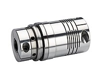
Safety coupling
A safety coupling protects prime movers from damage caused by e.g. B. can be caused by blocking or overloading the driven machines . In the event of overload, i.e. when the transmitted torque exceeds a permissible limit, the clutch separates both sides of the drive train from one another.
Safety couplings are offered for a wide range of maximum torques. The maximum permissible torque results from the specifications of the drive machine.
functionality
The torque transmission of a safety coupling takes place without play via hardened balls (4 ) which are arranged in conical countersinks (5) on one end face of the outer ring . These balls are pressed into the depressions by a plate spring (2) via a switching ring (3) .
With the adjusting nut (1), the pre-tensioning of the disc spring and thus the release torque can be continuously adjusted.
In the event of an overload, that is, when the torque transmitted via the clutch exceeds the disengagement torque, the balls are lifted out of the depressions against the contact pressure of the plate spring due to the conical shape of the depression. The input and output sides are then separated without any torque.
The axial movement of the switching ring in the event of an overload can be detected by a mechanical switch or a proximity switch (6) and used, for example, to control or regulate the drive machine.
Variants of safety couplings
Safety coupling angle-synchronous / ratcheting / locked
The coupling consists of two parts which are connected to one another by a ball bearing. The balls sit in a ball bed of one part and are adjusted and fixed by a plate spring (part 2). If the torque exceeds the permissible torque, the force of the disc spring is no longer sufficient to fix the balls in their bed. As a result, the balls leave their shape, which in turn means that the output side is separated from the drive side. If the overload becomes smaller, the force of the disc spring is again sufficient to fix the ball ⇒ non-positive connection.
Safety clutch disengaging
In the release version, the spring changes completely and pulls the switching ring away from the balls. The clutch now runs freely without connecting the input and output sides. The re-engagement does not take place automatically; it has to be done manually. There is also the variant with automatic re-engagement, for this purpose you reverse the direction of rotation on the input or output.
ATC / Active Torque Control shutdown
In addition to the purely mechanical locking clutch, there is the ATC quick shutdown system, which is used in Hilti hammer drill rigs . This ATC (Active Torque Control) offers additional protection in drilling operation through the rapid shutdown in the event of uncontrolled rotary movement of the device around the drill axis, as is the case with e.g. B. when jamming the drill at z. B. Armor hits or accidental tilting of the tool can occur. Only both safety systems “mech. Slip clutch and ATC “offer the best user / safety protection.
Areas of application for safety couplings
Safety couplings can be used in all types of machine tools. z. B. in:
- NC milling machines
- Woodworking machines
- Automation systems
- Industrial robots
- Sheet metal working machines
- Printing machines
- Textile machines
also in agriculture
to decouple the devices from the drive forces in the event of a blockage by foreign bodies.


