Signal flow diagram
In control engineering , the signal flow plan , also known as an action plan according to German industrial standards , helps to better understand complex systems . It is used to visualize and create a mathematical model using a block diagram . It therefore represents a special form of the block diagram that enables quantitative relationships to be recorded in a system. In particular, it contains, in addition to a normal block diagram, arrows that indicate the direction of action. For linear systems, the transfer function can easily be derived from the action plan.
With the help of conversion rules, a signal flow plan can be converted according to aspects such as physical structure, understanding of the interdependencies or according to perspectives (e.g. influence of disturbance variables).
With modern graphic tools, not only can signal flow plans be drawn, but computer-aided simulations can also be carried out. Graphic tools are therefore replacing text-based description languages.
Elements of a signal flow plan
Directed edges (sometimes also called lines of action), branches, addition points and blocks belong to a signal flow diagram .
An edge is represented by an arrow and symbolizes a signal that usually corresponds to a physical quantity. Edges can represent the input and output variables of a system or connect different elements within a system with one another. In mathematics, they correspond to assignments .
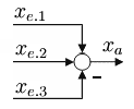
Branches are used to assign the same edge to several different blocks, adding points to combine several edges into a single one. If several edges are combined, they must represent the same physical quantity. The resulting edge then also represents this size.
| Edge | branch | Summation point | linear transmission link | non-linear transfer element |
|
|

|

|

|

|
| ; T = transformation |
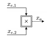
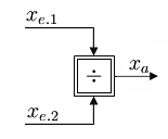
| Multiplication point | Division office | Transmission link described by symbol ( PT1 ) |

|

|

|
Transmission link
A block is also known as a transmission link. This has at least one input (cause) and one output (effect). The implementation takes place on the basis of the transmission property (link). Blocks are divided into typical transfer elements ( P element , I element , etc.), into blocks that carry a function and into non-linear transfer elements.
A transfer link is assumed to be non-reactive, i.e. the cause remains unaffected by its effect. If an element in the block diagram cannot be assumed to be free of reaction, this element must be represented in the signal flow diagram using several interconnected blocks. The reaction is modeled by circular structures ( see below ). If the transfer element fulfills the LZI conditions, its transfer function can be specified particularly easily.
Signal flow algebra
If a signal flow plan is to be redesigned, various rules must be observed when combining and moving elements.
Summary rules
The summary rules 'series connection' and 'dissolve circular structure' can only be applied to systems that have LZI properties. The summary rule 'parallel connection' can also be used for non-linear and time-variant transfer elements, but cannot then be formulated using the transfer functions.
In the following, G (s) stands for the transfer function of a continuous system. But, what is presented applies equally to the transfer function of a discrete system G (z).
Parallel connection
Series connection
Dissolve circular structure
Moving rules
The displacement rules can only be applied to systems that have LZI properties.
Move node
Move addition point
See also
literature
- Günther Schmidt : Fundamentals of control engineering . Springer Verlag, 1987, ISBN 3-540-17112-6
Individual evidence
- ↑ DIN 19226 control technology - regulation technology and control technology
Web links
- Training material from Samson AG (PDF file; 325 kB)
- Signal flow algebra (physics, Ulm University)


