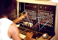
Patch panel (cabling)
A patch panel , including: patch bay is, in many areas of the wired data transmission (such as audio , telephone and video technology or computer networks ) a technical device to simplify cabling, normally several devices are connected to the, their compounds comfortable means of short patch cables can be produced and changed via sockets on the front .
While the sources and destinations are created as a matrix in functionally similar crossbars or switching matrices and can thus be interconnected as required ( n: m ), with patch panels, normally only one source can be assigned to a destination (1: 1).
The rear connections of the patch panels, which are usually not accessible during normal operation, vary - depending on the desired signal quality and the simplicity of the assignment, connectors (single or multicore ), spring clips or soldering lugs are used.
application
In the early days of telephony, calls were made manually by telephone operators by connecting the interlocutors with plug-in cables. The operators were also able to connect to the connectors directly on the patch panel using a headset.
In the audio and video sector, patch panels allow flexible cabling of signal outputs and inputs, for example the outputs of a mixer with a recording device or the looping in of effects devices . It is also possible to listen to signals at different points, for example to identify sources of error.
In building technology , patch panels (usually called patch panels ) are used in order to be able to interconnect all terminal device connections distributed over a larger area at a central point.
Operating modes
In order to make handling easier and to increase the clarity, patch panels can have certain signal paths internally preconfigured, which are also connected without cables being plugged in. This is useful, for example, with the microphone input of a mixer, where a preamplifier (integrated in the mixer or external), an equalizer and a compressor are often connected in series after the microphone . Each path between the individual devices is routed via a pair of sockets on the patch panel; the output of the previous device is usually on top, the input of the next on the bottom. With many devices, the type of looping through can be adjusted by the user; this can be done using switches, exchanging individual modules or soldering.
(Fully) normalized
The signal is looped through an internal bridge from the output to the input at a normalized pair of sockets without a connected cable. If a plug is inserted into one of the two sockets, the bridge is broken.
Semi-normalized
The pre-assigned connection of a semi-normalized patch path is also closed as long as no patch cable is plugged in. - If, however, a patch cable is plugged into the input - or - the output of the patch path, the pre-assigned connection remains closed anyway. - This allows either a parallel branching of the signal from the patch-out for further use (however with loss of level and quality), or a 50:50 mixing of a plugged-in signal via the patch-in (overloading of the following input, distortion).
Only when a patch cable is inserted in the input and in the output of a semi-normalized patch path is the pre-assigned path separated or replaced.
Parallel Patch Bay
There is a fixed connection in the patch path that cannot be interrupted by plugged-in patch cables. - A parallel branching (patch-out) and at the same time a merging (patch-in) is possible without interrupting the pre-assigned normalization. - No substitutions (inserts) are therefore possible, but at most 50:50 admixtures through amalgamation.
Open (abnormal) patch bay
When the configuration is open, there is no preassigned contact between the two sockets of a patch path. - Any signal flow must therefore be established via patch cables.
literature
- R. Beckmann: Manual of PA technology, basic component practice. 2nd edition, Elektor-Verlag, Aachen 1990, ISBN 3-921608-66-X
- Siegfried Wirsum: Practical sound technology, device concepts, installation, optimization. 1st edition, Franzis, Munich 1991, ISBN 3-7723-5862-4


