
Number slider
The number slider (also called pen adder ) is a simple arithmetic device for adding and subtracting numbers. It consists of several bars that can be moved in parallel in a flat housing, each of which is used for a position in the decimal place value system.
Two different operating areas are required for addition and subtraction. With some devices, these lie one below the other or the rods can be moved in both directions. Other devices have an area on the front and one on the back. Rods and housings are then shorter than with devices that can be used on one side.
Most devices are made of metal, simple versions are made of cardboard. A special feature is the combination of a slide rule and a number slide.
The number slide already existed in the 16th century. In 1847 it was completed by the German Hermann Kummer , who invented a semiautomatic ten carry . The number slide became generally known and used when the French Louis Troncet launched a version under the name Arithmographe in 1889 . Number sliders were built until they were replaced by the calculator in the 1980s . One of the best-known brands was the Addiator made in Germany , which became a synonym for number slider in the English-speaking world.

function
The bars are marked with a number from 0 to 9 in the middle along their length . One of these digits is visible as part of the calculation result through a small round window in the flat case. The bars are slotted on both long sides. Nine of the left slots are accessible from the outside through long, narrow windows in the housing. The narrow windows have a hook-shaped extension at one end. They look like a walking stick (clearly shown in the addiator , see below ). The slot currently underneath on the right long side of the rod adjacent to the left is accessible through the hook part, which means that the tens transfer that may be necessary during operation takes place on it. The bar on the left represents the next higher decimal place. The usual ranking system applies : The ones are on the far right. To the left, the tens, hundreds, etc. follow.
For arithmetic, the rods are moved lengthways with a stylus which is inserted into one of the left slots of a rod accessible through the narrow window. The slot to be selected corresponds to the numerical value to be added / subtracted and is found with the help of the number scale that is attached to the edge of each narrow window on the housing. The tens are used individually, the order being arbitrary.
Calculation example
The addition is carried out as follows (see adjacent figure, lower control panel):
- The initial display is 0 in all decimal places , which was achieved by pulling out (and pushing back) the bracket (at the top of the figure).
- Entering a 4 : Insert the stylus in the one-rod slot at the 4 on the housing scale and pull the rod down to the stop of the pen at the end of the window. The result 4 appears in the associated round window .
- Adding a 6 : Insert the stylus into the rod slot at the 6 on the housing scale. After entering the 4, there are bar slots marked in a different color at the 6 and higher as an indication that the bar “grasped” there must be pushed in the opposite direction (upwards). At the hook-shaped end of the window, the stylus tip leaves the rod slot and engages in a slot on the right-hand side of the ten rod adjacent to the left. The movement of the stylus, which is deflected at the hook end of the window, is continued downwards to the hook end, whereby the ten stick is taken from 0 to 1 according to the number 1. The unit rod had been pushed back to 0 (4−4), corresponding to the number 4 (addition of the addend 6 to 10), when the stylus tip disengaged. The result 10 has appeared in the two associated round windows , with a tens carried over from the ones to the tens.
- Further addition of an 83 : The processes are the same as in Step 2 (addition of the 3 on the ones stick) and Step 3 (addition of the 8 on the tens stick). The result of the addition is 93 .
- Further addition of an 8 : Insert the stylus into the slot of the one rod at the 8 on the housing scale and slide it upwards. The unit rod has been pushed back to 1 (3−2) according to the digit value 2 (addition of the summand 8 to 10) when the stylus tip disengages. When the stylus tip is hooked, the ten stick is pushed beyond 9 according to the number 1. The double transfer of tens via the tens to the hundreds rod is not yet over. In the round window of the tens rod, instead of a number, a colored area appears as a warning that the tens transfer has yet to be completed. Insert the stylus into the slot of the ten rod at 0 on the housing scale and slide it upwards. The ten stick is pushed back by 10 digits (total height of the narrow window) to 0 (9 + 1−10). When the stylus moves down the hook, the hundred rod is taken from 0 to 1 according to the number 1. The final result of the addition is 101 .
The subtraction is carried out from the upper control panel, which is a mirror image of the lower control panel, by moving the same bars. The processes are analogous to those with addition, whereby the directions of movement are also mirror images. Most number sliders cannot be used to calculate with a negative result. You can only subtract if a value that is greater or equal has been added beforehand. Special versions for possible negative balances have an extra result window for this. In addition, there is an additional row of numbers that is complementary to the previous row.
Number sliders, each with one control panel on the front and one on the back, are turned upside down between the two sides (turning around a transverse axis) (one rod remains on the right). This means that the directions of movement and the views of the two control panels are the same.
Model selection

Number slider with two control panels on the same side
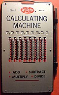
Wizard : number slider with one control panel on the same side (two parallel control panels)
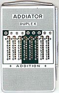
Addiator with control panels on two sides

Addiator with control panels on the same side

Addiator brand logo


Web links
- Interactive computer model of a two-sided slider addiator.de
- What is a number slider? addiator.de
- Number slider . rechnerlexikon.de
- Siegfried Wetzel: Number slide .
Individual evidence
- ↑ a b slide rule with number slide on the other side of Faber-Castell : beuth-hochschule.de and sliderules.info
- ↑ I. Thome: Abaque Rabdologique, inventé par Perrault . (PDF; 2.8 MB) In: Machines et Inventions approuvées par l'Academie Royale des Sciences , Part 1, Paris 1701 (illustration on last page)
- ↑ The Abaque Rabdologique of Perrault . history-computer.com
- ↑ Timo Leipälä: Kummer and his “1847” slide adder . (PDF; 3.6 MB) Lecture at the University of Greifswald on September 5, 2009 (revised December 2009)
- ↑ Arithmographe of Troncet
- ^ Business advertisement for the Addiator company from Berlin-Wilmersdorf . In: Berlin address book , 1921, before part 1.
- ↑ a b Interactive computer model of a two-sided number slide addiator.de