
Intermediate lift
An intermediate lift or remontoir d'egalité ( French for intermediate drive or tensioning mechanism ) is an energy storage device for mechanical clocks that does not drive the entire mechanism , but only the escape wheel or a wheel immediately in front of it ( seconds wheel in portable clocks) and is periodically charged (wound up) by the main energy source ) becomes. The escapement and thus the oscillation system ( pendulum , balance spring) are provided with a largely constant drive torque , which is the prerequisite for a constant oscillation period that determines the rate accuracy .
more details
Constructions in which the intermediate energy storage is part of the escapement and is charged for each oscillation or half-vibration of the vibrator or emits a drive pulse, are not referred to as intermediate lifts, but are counted as escapements. Examples are the gravity or spring escapement by Denison, Riefler and Strasser as well as the constant impulse escapement by Déhon (see escapement (clock) ). Even modern automatic watches are not watches with intermediate winding, because they do not have any intermediate energy storage, but the mainspring (main energy source) is tensioned irregularly (depending on the movement of the watch). Recently built clocks with an electrical intermediate winding system are not considered here.
Old pocket watches are often marked remontoire . As a rule, these watches do not have an intermediate winding system. It was customary to use this name to distinguish clocks with crown windings from the key windings previously used. Auxiliary drives that keep the clock running while the clock is being wound (this often takes hours with tower clocks) are also called remontoir . However, these drive the entire running gear and not just the escapement and must therefore be distinguished from the intermediate lifts.
The main energy source of a watch delivers a large drive torque over a long period of time (days, weeks), while the intermediate winding delivers a small torque necessary for the operation of the escapement and the oscillating system, whereby periodic reloading in short time cycles is necessary due to the low storage capacity.

Large clocks (tower clocks, floor clocks, table clocks, etc.) are usually driven with a weight and small clocks (pocket watches, wristwatches, alarm clocks, etc.) with a mainspring (coiled leaf spring). The mainspring drive has the disadvantage that a decreasing torque is emitted with increasing relaxation of the spring. In principle, the weight drive delivers a constant torque. Inaccuracies in the power transmission through the escapement mechanism, as well as other influences (dirt, weather conditions in the case of tower clocks, etc.) lead to a variable drive torque at the escapement. These disturbances are eliminated by the intermediate elevator and a largely constant torque is made available as long as the varying torque of the main drive is still able to charge the intermediate storage (point S, see figure). The torques emitted by the main energy source are much greater than shown in the picture because of the speed ratio in relation to the torques at the escapement.
The invention of the intermediate elevator is attributed to Jost Bürgi (early 17th century). As a result, many different designs have become known. In addition to the energy storage device (weight or spring), they all have in common a release and stop mechanism. As will be described below, the triggering represents an unavoidable disturbance that must be kept as small as possible by design measures. The movement of the drive does not take place in the time steps specified by the escape wheel, as is the case with watches without intermediate winding, but is determined by the winding period of the intermediate winding. If this is opened, for example, once per minute, the drive will only move a step further once per minute. The elapse of the time can therefore only be displayed in steps of one minute unless a pointer is attached to the escape wheel shaft or a (secondary) display drive is derived.
The intermediate winding has not established itself for portable watches, although it has been used sporadically in recent times. There are many reasons. In particular, the mechanics of the intermediate elevator represent an additional source of error (e.g. spring fatigue of the intermediate storage, friction problems of the release mechanism, etc.), so that the higher expenditure did not lead to any significant improvement in the accuracy. The intermediate lift is more common in large clocks (especially tower clocks).
The principles of some constructions are explained below.
Harrison spring-loaded intermediate elevator
John Harrison (watchmaker) used an intermediate lift for his marine chronometer H2 as shown in the adjacent picture

The shafts 1 to 4 are mounted in a frame, not shown. The grasshopper inhibition GH, which is not of interest here , on the one hand allows the escapement wheel HR to run in step with the oscillating system, which is also not shown (with Harrison tension spring-coupled cross-beat balance beam) and, on the other hand, supplies the oscillating system with periodic drive pulses to maintain the oscillation. The escape wheel and two cam disks KS are firmly seated on the shaft 1. Two tension springs F are attached to the cam disks, which are connected at their other end to a tensioning wheel SR via pins ST. Tensioning wheel, a pinion RZ1 and a star switch SS are connected to the hollow shaft HW, which can rotate on the shaft 1. The tension springs exert a counterclockwise torque on the escape wheel. While the escape wheel and thus also the cam discs move continuously, the movement of the tensioning wheel is blocked by a locking piece SP attached to the double lever DH, the double lever constantly resting on the star switch because of the weight G. The tension springs thus relax and deliver increasingly less force. However, since the shortening spring lengths f (f1, f2) are opposed to increasing lever arms a (a1, a2), the driving torque remains largely constant. The springs are re-tensioned periodically after the escape wheel has turned a certain angle, i.e. after a certain time (with Harrison it is 30 seconds). This process is triggered by one of the cams N on the escape wheel, which acts on the SF button of the double lever and thus lifts the locking piece from the star switch. The escape wheel must do the so-called release work against the weight of the lever and against frictional forces. This reduces the driving torque supplied by the tension springs so that a lower drive pulse is supplied to the oscillating system during the release process. By optimizing the design of the release mechanism (or stop mechanism), the release work must be minimized in order to keep the (negative) influence on the rate accuracy as small as possible. Since the locking piece no longer blocks the star switch, the drive torque supplied by the main energy source is transferred from the drive wheel LW, which has been stationary until then, to the pinion and thus the tensioning wheel, which now moves counterclockwise and re-tensions the springs. So that this movement does not take place too quickly, a porch W is driven with the pinion RZ2. After the cam of the escape wheel has left the button of the double lever, the locking piece of the double lever engages again in the star switch and ends the re-tensioning. The drive has stopped again. The drive of the escape wheel by the springs was not interrupted during the entire retensioning process.
Gravity intermediate elevator from Wagner
Another solution used for large clocks comes from Bernard-Henri Wagner. The principle is shown in the picture opposite.
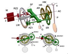
The shafts 1 to 4 are stored in the frame, not shown. The shafts 1 and 2 lie on the common axis AC. A climbing wheel SR and a pinion RZ1 are fastened on the shaft 5, the shaft being mounted in a balanced lever H which can rotate freely around the shaft 1. The climbing wheel engages a drive wheel AR which, like the escape wheel HR, is firmly seated on the shaft 2. The escape wheel is periodically released and stopped by the escapement HM according to the period of oscillation of the pendulum. The gear LW driven by the main energy source via the drive continuously exerts a torque on the pinion RZ2, which, like two shift fingers SF and a vestibule W, is firmly connected to the shaft 3. Under the influence of the torque, a switch finger rests on the cylindrical part of a switch cam SN connected to the lever and thus prevents movement of the wheel LW or the drive. The switching cam has a recess A which, when the lever is rotated by a certain amount, releases the respective switching finger, allowing the drive to move. The weight G is attached to the lever. The weight raised by the lever represents the intermediate energy store and exerts a torque about the axis AC.
The raised lever can only move downwards under the influence of this torque when the escapement releases the escape wheel and thus the drive wheel. When the escape wheel is stopped, the lever movement is blocked, because the steering wheel and the pinion RZ1 can only move by the same angular amounts due to the fixed connection with the shaft 5. When rolling on its fixed counter-wheels by this angular amount, the lever would have to move around the axis AC at different angles due to the different diameters of SR and RZ1, which is not possible.
If SR and RZ1 were the same size (and therefore LW and AR the same size), the lever would move downwards unhindered by rolling the wheels even with the escape wheel held.
If the escape wheel is released, the rolling movement from SR to AR is not completely converted into an angular movement of the lever, as part of the movement is transferred to AR. This compensating differential movement enables the lever to move since the same angular movements of RZ1 and SR do not conflict with mutually exclusive movement conditions for the lever.
The weight creates a permanent (small) torque that provides a sufficiently large drive impulse for the escapement or the pendulum. On the climbing wheel, this moment acts in a clockwise direction, so that a moment counterclockwise is applied to the drive wheel and thus to the escape wheel without interruption. Each time the escapement wheel is released, it moves by the amount specified by the escapement and the lever gradually descends, releasing energy to the escapement wheel or the pendulum with the rotating wheels SR and RZ1. In the lower end position, the switching cam releases the switching wing. LW moves counterclockwise and, since SR is intermittently blocked by AR (or HR), raises the lever in one quick movement. SR rolls counterclockwise onto AR, with only the moment determined by G acting on AR via SR. The escape wheel continues to be driven evenly during this process and the drive impulse for the pendulum remains constant. The rapid movement of the lever or LW is dampened by the porch. After RZ2 has completed half a turn, the other switching wing hits the switching cam, which ends the opening. An animation and videos are available at.
Since the horizontal distance to shaft 1 (lever arm) changes when the lever is moved, the torque delivered to the escape wheel is not constant. As with Harrison, this could be remedied by running the rope holding the weight over a cam attached to the lever.
Intermediate gravity elevator from Robin
The intermediate winding invented by Robert Robin is based on the remontoire attributed to Christiaan Huygens , i.e., as mentioned above, a device for maintaining the drive torque while the watch is being wound. The function of this auxiliary drive can be seen in the adjacent picture.

With an endless traction mechanism (usually a chain), two loose rollers LR are connected to a wheel LW driving the clock drive and a winding wheel AZ. The rollers and wheels are usually designed as gear wheels. Two weights of different sizes G1 and G2 hang from the loose rollers. As shown, forces of different magnitude thus act on the wheel LW via the traction means, so that a drive torque in a clockwise direction
M = 0.5 (G1-G2) r
takes effect. As the clock is running, G1 goes down and G2 moves up. To wind the watch, the winding wheel is rotated counterclockwise, whereby G1 is raised and G2 is lowered. The drive torque acting on the wheel LW is not influenced during this process, so that a constant drive of the clock is guaranteed.

On this basis, Robin designed an intermediate elevator (see adjacent picture). It is not the drive, but the drive wheel AR in front of the escape wheel HR that is driven with a constant torque. The weights are much smaller than with Huygens, since the drive only has to maintain the oscillation of the pendulum P with the help of the escapement HM and does not have to drive the entire drive. The intermediate elevator is periodically pulled up by the running gear, which is driven by the main drive source (large weight or mainspring). The drive transmits its torque via the wheel LW to the intermediate wheel ZR, which is responsible for raising G1 or lowering G2. A simple mechanism ensures that winding only takes place when G1 has reached its lowest point. G1 then touches the pressure piece DS. A linkage consisting of the lever H1 and the shift lever SH and the connecting piece H2 articulated therewith, which is mounted at A and B in the frame (not shown), is thereby deflected from its rest position (release work). The shift lever turns around B and its stop releases the shift pin ST attached to the wheel LW. LW rotates counter-clockwise and pulls the intermediate lift on ZR. During this process, the weight HG ensures that the linkage returns to its rest position, which is characterized by the fact that the switching lever is in contact with the stop AS. The wheel LW is thus stopped again after one revolution, since ST then strikes the stop of the shift lever. The drive runs down step by step with the consequences for the time display already mentioned above. The main drive source itself must of course also be drawn up at greater intervals. A second Huygensian system (with large weights) can be used to keep the clock running.
A realization of the intermediate lift as shown in the picture is only useful for small weight lifts, since the drive torque is not constant when the weights are moved because of the changing direction of the rope forces (force diagram). For this reason, the diameter of the rollers and wheel spacing are often chosen in practice so that the ropes or chain strands run parallel and thus the drive torque remains constant.
Spring tension intermediate elevator from Lange
In the middle of the 19th century, Ferdinand Adolph Lange developed an intermediate winding system suitable for pocket watches that was used in his company's clocks. The principle can be seen in the picture opposite.

The shafts 1 to 4 are stored in the frame, not shown. A spring wheel SR with six teeth (stops) sits, like a spiral roller SPR, firmly on the shaft1. A drive spring AS (spiral spring; not to be confused with the spiral US of the balance U), which represents the intermediate energy storage, is attached to the spiral roller with its inner end. On the shaft 1, the escape wheel HR and the release wheel ALR, which are firmly connected to one another, can rotate freely as a hollow shaft. Like the jumping wheel, the release wheel has six teeth. A spiral block SK is attached to the escape wheel, to which the outer end of the drive spring is attached. The drive spring is pretensioned between the escape wheel and the jumping wheel (by turning the wheels against each other) so that the torque it generates is sufficient to drive the escapement (the armature) and thus give the balance a drive impulse when the jumping wheel is stationary. The torque provided by the main energy source (mainspring), which is transmitted from the drive (not shown) to the drive wheel, constantly acts on the jumping wheel via the drive wheel AR that is firmly connected to it. The jumping wheel is prevented from rotating by the lower arm UHA of a double lever, against whose rest stone RST a tooth of the jumping wheel rests. The upper arm OHA of the double lever is constantly pressed lightly against the release wheel by a spring BF (leaf spring). The escape wheel, driven by the drive spring and periodically inhibited by the armature A, decelerates gradually. The mainspring relaxes. The release wheel rotates synchronously with the escape wheel and lifts the upper lever arm of the double lever with one of its teeth (inclined plane) so that the rest stone on the lower lever arm releases the jumping wheel (release work). This rotates very quickly, driven by the drive, and re-tensions the drive spring by rotating the spiral roller (the inner end of the spiral). The drive spring does not deliver a constant torque to the escape wheel, since it relaxes again and again between the re-tensioning processes (spring characteristic). In the diagram, the torque would thus have a sawtooth-like curve.
The transmission ratio from the second wheel (not shown), which rotates once per minute, to the drive wheel is 1:10. Since the jumping wheel moves in six steps (6 teeth) per revolution, the second wheel performs 60 steps per minute. This is known as the “jumping second” because the second hand on the fourth wheel shaft moves once per second. This display is standard in today's quartz watches, but was only possible with small mechanical watches (pocket watches, wristwatches) through the use of an intermediate winding system. The second hand usually moves with the step frequency of the escape wheel, so that the second hand advances in several partial steps per second (usually five).
Modern developments
As far as is known, modern temporary storage constructions for small watches (wristwatches), like FA Lange, use a spiral spring as the drive spring. However, different types of switching mechanisms are used. A recent example is shown schematically in the picture opposite (for more, see).

The shafts 1 to 5 are mounted in a frame, not shown. The spiral roller SR and the drive wheel AR are firmly connected to the shaft 2 and thus rotate together. A so-called Gleichdick GD (Reuleaux cam) sits firmly on the escape wheel HR. Both rotate freely on shaft 2 as a hollow shaft. The same thickness runs in the fork of a shift lever SH, which can rotate around shaft 1.
A constant thickness is used because when it rotates it behaves like an eccentrically mounted cylinder (which is easier to manufacture) (the fork moves back and forth without changing play), but does not have an eccentric center of gravity. In the case of portable watches, this would lead to an undesirable torque being exerted on the escape wheel in different positions.
The shift lever carries two pallets PA which, when the lever is moved, alternately come into engagement with the ratchet wheel SRA, which has a ratchet tooth SZ. The ratchet wheel is continuously acted upon with a counterclockwise torque via the drive wheel LW driven by the main energy store (mainspring). The ratchet wheel cannot rotate as long as the ratchet tooth rests on one of the two pallets of the shift lever. The drive spring AS (spiral spring) is connected at its inner end to the spiral roller and at its outer end to a spiral block SK attached to the escape wheel. There is no further connection between the drive wheel and the escape wheel. The drive spring is pre-tensioned between the drive wheel and the escape wheel (by turning the wheels against each other), which drives the escape wheel and is sufficient to provide the balance-wheel-spiral oscillation system with a drive pulse that maintains the oscillation via the armature.
The escape wheel, driven by the drive spring and periodically inhibited by the armature A, decelerates gradually. The mainspring relaxes. During this process, the mainspring must also do the triggering work. This consists in the fork having to be moved against the frictional resistance between the switching tooth and the pallet. In contrast to other triggering mechanisms, the work that has to be performed without interruption is an advantage because there is no torque drop when triggered. After the escape wheel has rotated 180 °, one pallet releases the switching tooth, while the other has already been moved into the catch position for the switching tooth. The ratchet wheel now moves through 180 °, driven by the drive, until the ratchet tooth hits the pallet. The drive spring is also retensioned by 180 °. As already described in Lange, the step-by-step drive is used to display the “jumping second”.
An animation can be found under.
The drive spring does not deliver a constant torque to the escape wheel, since it relaxes again and again between the re-tensioning processes (spring characteristic). In the diagram, the torque would thus have a sawtooth-like curve. Therefore, as Harrison did, various mechanisms are used to eliminate this disadvantage. What they all have in common is that the decreasing spring force is countered by an increasing effective lever arm. The torque acting on the escape wheel as the product of force and lever arm then remains largely constant.
Such a construction is explained with the adjacent picture, which is suitable for re-tensioning angles <90 ° (here 45 °).

A clamping ring SR is firmly connected to the drive wheel AR and an eccentric EX. Depending on the ratchet wheel (not shown), the drive wheel and the clamping ring move step by step, driven by the drive. The outer end of the spiral drive AS is attached to the tension ring with a pin. The clamping ring can rotate freely on the shaft 1 as a hollow shaft. The escape wheel HR is firmly connected to the shaft 1 and a pin holder SH for the drive pin TS. The pen holder is designed with a counterweight in such a way that its center of gravity coincides with the shaft axis and thus no undesired torques arise when the position of the watch is changed. The inner end of the drive spring is attached to a spiral roller SR which can rotate freely on the shaft 1. The drive pin AST is attached to the spiral roller. The force balancing disk KA is provided with two arms, the pin contact surfaces of which form a plane in which the eccentric axis lies.
The drive spring pretensioned between the tension ring and the spiral roller exerts a drive torque (when the tension ring is stationary) via the spiral roller and the drive pin on the force compensation disc. So there is no direct action of the mainspring on the escape wheel. Only the force compensation disc acts with the same torque on the drive pin TS and thus the escape wheel. The re-tensioned drive spring delivers the moment F1 ∙ a (phase 1). The escapement wheel now, intermittently inhibited by the escapement and driven by the drive torque, runs down gradually, with the force of the drive spring continuously decreasing (the tensioning wheel stands still). With the escape wheel, the force compensation disc also rotates gradually, but around the eccentric axis. This increases the effective lever arm (shown in phase 2 after the escape wheel has moved 45 °; b> a; F2 <F1), so that the drive torque remains approximately constant. The clamping ring is now released by the ratchet wheel, which is driven by the drive, rotated by 45 ° and retensioned the drive spring (phase 3). The process will now start again.
In addition to the higher effort required for the force compensation, the particular disadvantage of this construction is that the pins on the arms of the force compensation disk constantly move relative to the latter (friction).
As already mentioned at the beginning, with portable watches it is at least questionable whether a better time measurement result can be achieved by using an intermediate winding system.
Individual evidence
- ↑ Klaus Menny: The clock and its mechanics. Retrieved August 31, 2016 .
- ↑ Ken Kuo: Wagner Remontoire. April 5, 2016, accessed August 31, 2016 .
- ^ Remontoir Wagner. Retrieved August 31, 2016 .
- ^ Mark Frank: The Evolution of Tower Clock Movements and their design over the past 1000 years. Retrieved August 31, 2016 .
- ↑ Richard Lange: A. Lange's clock with constant force. Retrieved August 31, 2016 .
- ↑ Jean-Francois Mojon: Constant force device . Retrieved August 31, 2016 .
- ↑ Girardin, JF; Forsey, SEM: PM. Retrieved August 31, 2016 .
- ↑ Andreas Strehler: Power transmission mechanism of a mechanical clockwork. Retrieved on June 18, 2019 (click on "Load full document" after calling up).
- ↑ Andreas Strehler: Drive mechanism for a clock. Retrieved on June 18, 2019 (click on "Load full document" after calling up).
- ↑ Jens Schneider: Clock. Retrieved on June 18, 2019 (click on "Load full document" after calling up).
- ↑ Lange31 back-end 3D animation. Retrieved November 12, 2016 .