Beamforming

(the black circles in the background)
in an aeroacoustic wind tunnel
( FKFS , Stuttgart)
Beamforming (literally "beam shaping") is a method for determining the position of sources in wave fields (e.g. sound fields ). Corresponding devices are also called acoustic cameras , microphone arrays or acoustic antennas .
For use with antennas s. u.
In acoustics
In the acoustic beam forming is usually used when measurements are possible in the vicinity of the object, or only with great effort, for. B. with landing planes or passing trains. This is why the term “acoustic telescope” has already been introduced in the relevant literature.
The microphone is usually arranged on a flat surface, usually linear, cross, ring or spiral, e.g. T. also quasi-randomly distributed.
Measuring principle
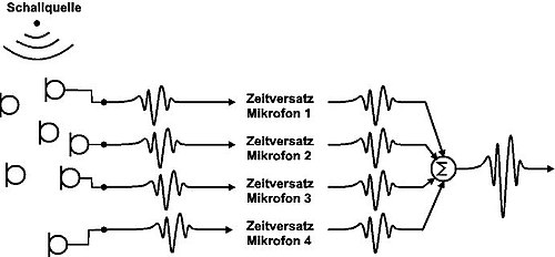
The measuring principle is based on the fact that the microphone array is focused on the different measuring points on the measuring object. This is done by a time shift of the sound signals recorded by the respective microphone , which corresponds to the transit time from the measuring point to this microphone. Sound transit times can be converted into distances by multiplying them by the speed of sound .
The time-corrected signals from all microphones are summed up, resulting in a time signal assigned to the respective measuring point (i.e. signal curve over time). The sound from sources at other positions is attenuated , as their signals are no longer fully time-corrected and sometimes overlap destructively ; however, the sound emitted from the respective measuring point (focus point) is amplified.
The quality of the beamformer is often increased through the use of complex digital filters .
The frequency range of beamforming arrays is limited downwards by the array size: the larger the array, the lower its cutoff frequency .
The upper limit of the frequency range is due to the increasing occurrence of apparent sound sources ( aliasing effect ). These occur particularly with regularly arranged microphones and lead to misinterpretations. The cut-off frequency above which these phenomena occur is higher, the smaller the distance between the microphones is.
The meaning of the sound sources is usually shown in a color code and superimposed on a conventional video image of the measurement object. In this way, the positions of the main sound sources can be easily recognized. Frequency-selective displays are also possible.
Applications
- Localization and evaluation of sound sources
- Masking out sources of interference ; this works on the same principle as the localization, but the filters are optimized to suppress the sound emitted from one or more locations as best as possible, e.g. Example in mobile phone - hands-free devices in vehicles.
Beamforming Network for antennas
The term beamforming network (BFN) used in antennas for electromagnetic radiation stands for a circuit that adapts the radiation profile of an antenna to any geometric contour.
In the case of symmetrically radiating group antennas such as yagi or phased array antennas , the term beamforming network is not used ; see also MIMO .
The antennas of modern television satellites have a radiation profile that is based on the contour of the land on which the signals are to be received. To do this, several feeds shine on a common parabolic reflector . A correspondingly shaped secondary reflector is interposed for fine adjustment.
See also
literature
- U. Michel, M. Möser: Acoustic antennas. In: Measurement technology of acoustics. Springer, Berlin / Heidelberg 2010, ISBN 978-3-540-68086-4 , pp. 365-425.
- JJ Christensen, J. Hald: Beamforming . Technical Review No. 1/2004, Brüel & Kjær Sound & Vibration Measurement A / S, Nærum, Denmark, 2004 (see "Weblinks")
- J. Billingsley, R. Kinns: The acoustic telescope. In: Journal of Sound and Vibration. Volume 48, No. 4, 1976, pp. 485-510.
- PT Soderman, SC Noble: A Directional Microphone Array for Acoustic Studies of Wind Tunnel Models . AIAA Paper 74-640, AIAA Aerodynamic Testing Conference, 8th, Bethesda, Md., July 8-10, 1974.
Web links
- The website of the Berlin Beamforming Conference with further English-language literature
- Use of an acoustic camera for NVH optimization of the engine and drive train (PDF file; 870 kB)
- Localization of transient sound sources (PDF file; 401 kB)
- Beamforming using three-dimensional microphone arrays (PDF file; 2.8 MB)
- Real-time audio signal enhancement for hands-free speech applications (PDF file; 239 kB)
- Identifying Acoustic Bridges By Using Beamforming And Sound Intensity In SITU Measurement Technique (PDF file; 1.2 MB)
- Red means "noise" - acoustic camera detects sources of noise , contribution from the program nano on 3sat on Friday, March 5th, 2010
- Automatic directional radar microphone for voice control on Heise online from February 28, 2017

