
Föttinger principle
The Föttinger principle ( Föttinger converter , Föttinger gearbox , torque converter ) in its original form consists in the coupling of a drive shaft with an output shaft via a circulating fluid (oil, water, etc.) to transmit a rotary movement ( torque ). For this purpose, a pump wheel (connected to the drive shaft) and a turbine wheel (connected to the output shaft) are arranged rotatably (mostly in alignment) in a sealed, fluid-filled housing at a short distance, but without contact, with the fluid flow from the outlet of the turbine wheel via a stationary Guide device is returned to the input of the pump wheel. The wheels and the guide device are designed in such a way that the fluid flow takes place on curved paths with a continuous change in curvature, so that a largely shock-free and loss-free flow can be achieved.
Before the invention of the principle by Hermann Föttinger, there was already fluid coupling of waves. However, in this case, a pump connected to the drive shaft was fed with the fluid from a reservoir, which was directed via pipes to the turbine connected to the output shaft and from there back into the reservoir. Föttinger has designed a compact assembly from this arrangement, which is lossy in terms of energy, in particular due to the pipelines, and requires large installation space.
The large number of possible construction variants can be traced back to three principles, the further development of which is still being carried out and for which new application possibilities are still being developed (e.g. in wind turbines ):
- Föttinger gearbox (Föttinger converter)
- Hydrodynamic coupling
- Trilok system
Föttinger transmission ( torque converter )
At the beginning of the 20th century, Föttinger set himself the task of connecting a ship's drive (steam turbine) to a ship's propeller with the help of a hydrodynamic converter (later called Föttinger converter) . Such drives and propellers, however, have different optimal speeds (the propeller should run much slower than the turbine). The converter had to transmit a torque with a certain speed reduction from the turbine to the propeller. It was also necessary to reverse the direction of rotation of the propeller (forward and reverse).
In his patent from 1905, the principle he selected and a large number of variants are specified. The principle is qualitatively explained using the accompanying (schematic) images. Euler's turbine equation provides quantitative information (see turbine ).

Fig. 1: Structure of the Föttinger converter
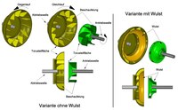
Fig. 2: Details of the Föttinger converter

Fig. 3: Flow in the Föttinger converter

Fig. 4: Characteristic curves of the Föttinger converter
The components of the converter are shown in Figure 1. The drive shaft is driven by a prime mover (motor, turbine, etc.). A pump wheel, which is shown here as a partial surface of a torus , is attached to the shaft (other rotationally symmetrical shapes are possible). The pump wheel is connected to a bead via blades ( not shown ) (see Fig. 2). A turbine wheel is constructed in the same way and attached to the output shaft. A stationary housing, sealed off from the shafts, encloses the wheels and carries the guide device, which is also provided with blades (not shown). The wheels and the guide device are separated from one another by narrow gaps and do not touch. The entire interior of the housing (including the cavities formed by the wheels and the guide device) is filled with oil. In real constructions, the housing is designed in such a way that there is only little "dead space".
When the pump wheel rotates, the fluid is mainly accelerated radially by the blades, so that a flow occurs between the toroidal surface and the bead, which flows into the turbine wheel. There it meets its blading and sets the previously stationary wheel turning. A torque is transmitted. The torus surface of the turbine wheel deflects the flow so that it is now mainly guided axially into the guide device. Here, too, there is a deflection, which leads to an axial flow into the pump wheel. An annular flow is created. However, the current paths do not run in one plane, but are spatially twisted.
In the course of development it has been found that the flow can also develop without the respective bead and that this can therefore be dispensed with. The bead variant is not considered in the further explanations.
The blading is optimally designed in accordance with the findings of pump and turbine technology and can have very different shapes (adjustable blades of the guide device are also possible). The blades are only shown schematically in the pictures.
It is a so-called PTL system. Pump wheel, turbine wheel and guide device are flowed through in this order.
From Fig. 2 (pump and turbine wheel not joined together) it can be seen that the turbine wheel can rotate in the opposite direction with respect to the pump wheel (reverse gear) if the pump wheel blades shown there have the opposite inclination. That was important for Föttinger's task (ship propulsion).
The relationships are shown in more detail in Figure 3. The impeller rotates at the peripheral velocity u P . Between its blades, the flow S is P (relative to the blades) with the exit velocity w P out. This is shown in simplified form. In reality, the exit direction varies between the blades (see turbine).
Since the flow S P is now, as it were, carried along by the rotating blades, the resulting exit velocity c P results , with which the flow hits the turbine blades of the turbine wheel which is still at rest. The flowing mass S T is deflected at the turbine blades, which, according to Newton , results in a force (i.e. a torque ) on the turbine wheel. The torques of the pump wheel and turbine wheel are in equilibrium ( actio = reactio ) for all operating states (speeds ). The turbine wheel begins to rotate. However, the faster it rotates, the less the deflection of the flow on the blades and thus the force effect becomes. If the pump and turbine wheel rotate at the same speed, no power and therefore no more torque is transmitted. For torque transmission, there must always be a difference in speed between the turbine and pump wheel. In the technical language this is called slip .
The flow S T is now deflected at the toroidal surface of the turbine wheel and, when it passes into the guide device, has the speed w T in the axial direction relative to the blades . As with the pump wheel, however, the flowing mass is carried along by the blades at the circumferential speed u T , so that the flow hits the stationary guide vanes at the speed c T when it exits the turbine wheel . These are designed so that the flow is slowed down and pushed more towards the turbine blades. This is indicated by arrows in the picture. The effect of this change in flow on the turbine wheel torque is referred to as the guide device torque M L. With a suitably directed flow change (as assumed here), the turbine torque increases and M L has a positive sign in the following equation (increase in torque M T ). However, under certain conditions it can also turn negative.
M T = M P + M L
The guide device thus increases the torque effective on the turbine wheel and changes the torque equilibrium of the pump and turbine wheel that exists without a guide device.
One can clearly imagine that if there are no guide vanes, the flow is deflected from the torus surface without any obstacles and can flow back to the pump wheel. In the presence of the damming outflow channels of the diffuser, the dammed flow looks for a further outflow by turning the turbine wheel faster, i.e. generating a higher torque on the turbine wheel with the same load on the output.
The flow is returned to the impeller through the guide vanes and is directed there to the rear of the impeller vanes, which also increases the torque.
The torque at the turbine wheel can be 2.5 times the pump wheel torque. However, the effect weakens with increasing turbine speed.
In addition to the torque, the efficiency is an important parameter. It is the ratio of the output from the turbine wheel to the output from the pump wheel (max. = 1). The size of the services does not matter, only their ratio! The power in rotating machines is calculated from the product of torque M and angular velocity ω.
Power: N = Mω
Efficiency: η = N T / N P = M T ω T / M P ω P
After what has been said above, the characteristics shown in Figure 4 result for the Föttinger converter . The motor or pump wheel speed and the motor torque and pump wheel torque are constant. The torque at the turbine wheel is greatest when it is at a standstill and falls almost linearly to zero as the speed ratio increases (max. = 1), i.e. the slip decreases. The efficiency is zero when the turbine wheel is at a standstill (angular speed ω T = 0) and passes through a maximum as the turbine wheel speed rises, only to drop to zero when the speed is the same ( turbine wheel torque M T = 0).
A vehicle driven by a Föttinger converter (e.g. a car) therefore delivers the desired high torque when starting, which is gently transmitted to the output due to the fluid coupling (starting aid). With increasing speed (turbine wheel speed) the torque decreases automatically and the efficiency improves. If the driving resistance is higher (speed reduction on the turbine wheel), the torque is automatically increased again. This principle is therefore a torque converter. The torque adapts itself (steplessly) to the load condition by changing the output speed.
The disadvantage, however, is that when the driving resistance is low (pump wheel speed and turbine wheel speed almost the same, slip practically zero), only a small amount of power is delivered to the turbine wheel, but the pump wheel still has to provide considerable power, since the fluid circulation against the resistance of the guide device (braking the oil flow) must be maintained (acceleration of the braked oil flow). The Trilok system listed below eliminates this deficiency.
For a ship propulsion system, Föttinger had developed a two-stage converter in accordance with its task, in which each stage could be filled or emptied with oil by an external pump via a control slide. One stage was designed for forward travel, the other for reverse travel. Only the oil-filled stage became effective, while the other one ran empty. However, the converter could not establish itself for ship propulsion.
Hydrodynamic coupling (speed converter)

Fig. 5: Structure of a hydrodynamic coupling

Fig. 6: Characteristic curves of a hydrodynamic coupling
Föttinger does not seem to have considered using his idea as a coupling. The name is not mentioned in the corresponding patent application of his former employer, although the application was made on the same day and with drawings of the Föttinger patent.
In contrast to the converter, the hydrodynamic coupling does not have a guide device. Pump wheel and turbine wheel face each other (Fig. 5). The blading of the wheels is usually radial. Usually one of the two wheels is connected to the housing so that it rotates with the respective wheel.
As with the converter, there is an annular flow from the pump wheel to the turbine wheel and back, and torque is transmitted. Since the guide device is missing, the turbine wheel torque according to the above explanations is always the same as the pump wheel torque (regardless of the magnitude of the torque).
M T = M P
This can be clearly explained by the fact that a certain mass of liquid is accelerated in the pump wheel. The same mass is braked again in the turbine wheel.
Slip is again required for torque transmission. The centrifugal forces of the turbine wheel acting on the flow are opposite to those of the pump wheel (in contrast to the converter) and have a greater effect as the speed of the turbine wheel increases. The transmittable torque therefore drops more sharply with increasing speed than with the converter (see characteristics). At the same speed of the pump and turbine wheel, no more torque is transmitted and there is also no more annular flow, since the centrifugal forces of both wheels acting on the flow cancel each other out. The fluid then circulates practically as a rigid mass with the wheels.
The clutch characteristics can be influenced by only partial filling with oil. By supplying and removing oil with an external pump, the oil level can be changed during operation or a constant oil exchange or circulation (e.g. for cooling) can be implemented. Since the housing rotates with most designs, the oil is supplied and discharged via the hollow shaft designed as a hollow shaft.
The efficiency increases as the speed difference between the wheels decreases. When the turbine wheel is stationary, ω T = 0 and thus η = 0. As the speed ratio increases, the angular speeds of both wheels approach more and more when the torques are equal (slip is smaller), so that the efficiency increases linearly (see characteristic curves).
η = N T / N P = M T ω T / M P ω P = ω T / ω P
Since the clutch reacts with a greater or lesser slip when the external load torque rises or falls (M T and M P and thus the engine torque change accordingly), the clutch is a speed converter (torque transformer) which automatically and continuously adjusts the required output speed at a constant engine speed . The drive machine must be able to generate the required torque.
application areas
- Traction help
Load-free start-up of vehicles and machines, wear-free start-up, gentle operation of heavy machinery (mining)
- Overload and blocking protection
The clutch can only transmit a limited maximum torque. The drive shaft is dimensioned so that there is definitely no risk of breakage at this moment. If the output shaft suddenly blocks (e.g. if an excavator hits an obstacle), the drive shaft continues to rotate without damage.
- Brake (retarder)
In this case, the turbine wheel cannot rotate (connected to the fixed housing). The drive shaft works against the maximum torque of the clutch and is braked by it. The braking energy is converted into heat, so that the oil must be constantly circulated by an external pump and fed to a cooling device.
Trilok system

Figure 7: Spannhake patent (slightly changed)

Fig. 8: Structure of the Trilok system
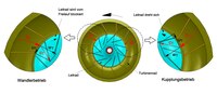
Fig. 9: Current in the Trilok system

Fig. 10: Characteristic curves of the Trilok system
With constant drive values (n P , M P ), an ideal automatic gearbox adapts the output torque M T to the requirements, with the output speed n T inevitably changing. The Föttinger converter fulfills this requirement over a large load range. In the event of a low external load (turbine speed n T large), however, the pump wheel and thus the driving engine must continue to generate power, since the ring current in the converter is maintained against the resistance of the diffuser. The efficiency is therefore poor in this area (see characteristic curve of the Föttinger converter).
A working group consisting of W. Spannhake, H. Kluge and K. von Sanden, which gave itself the name Trilok, developed the Trilok system from 1929 on the basis of a patent from the former.
The basic idea formulated in the patent is that in addition to the pump and turbine wheel, the diffuser is also designed as a moving wheel and all three wheels can be connected to other components either temporarily or permanently via couplings (fixed connections, mechanical couplings or brakes) ( see picture 7). Of course, only those couplings are provided that are necessary for the solution of a specific task. The wheels 1 to 3 can act as a pump, turbine or guide wheel as required.
A Föttinger converter is created from the scheme given if the coupling points K2 and K8 represent a fixed connection between the output shaft and wheel 3 (turbine wheel) and wheel 2 (pump wheel) is permanently connected to the drive shaft via K7, whereby wheel 1 (stator ) sits firmly on the housing via K5 and therefore cannot turn. All other couplings are omitted. Some other variants can be found in the patent.
In the Trilok system, wheel 1 is designed as a guide wheel (see Figure 8). As with the Föttinger converter, the other two wheels are connected to the input and output shaft. The special feature of the Trilok variant is that the coupling point K5 is a freewheel , which allows the stator to rotate only in the direction of the turbine wheel.
In principle, this is achieved structurally in such a way that the freewheel is attached to a hollow shaft that is firmly connected to a stationary housing. The drive shaft protrudes through this hollow shaft to the pump wheel. The turbine wheel drives the output shaft via the rotating housing (Fig. 8).
The situation is shown schematically in Figure 9. In converter operation (low to medium output speed) the system behaves like a Föttinger converter. Which (as described above) from the flow to the turbine wheel blades w relative T and the peripheral speed of the turbine wheel and T resulting resultant flow at the speed c T encounters the stator blades and searches the stator against the Turbinenraddrehsinn to rotate which because of the blocking by freewheeling is not possible. As explained for the Föttinger converter, the stator changes the flow and increases the torque on the turbine wheel (torque conversion). When the turbine wheel speed increases and further approaches the pump wheel speed, the flow direction c T changes . The flow now runs parallel to the front of the stator blades and hits the rear. The stator can now, released from the freewheel, rotate and moves practically at the same speed as the turbine wheel. Coupling conditions are established, ie in the annular flow the centrifugal forces acting against each other compensate each other more and more, so that they come to a standstill. The oil rotates with the three wheels moving at (almost) identical speed. The pump wheel no longer has to generate power to maintain the annular flow, which leads to a high degree of efficiency. At the same speed of the wheels, almost efficiency 1 is achieved. The connection between the drive and output shafts can then be viewed as almost rigid.
The system is supplemented by the use of a converter lock-up clutch by combining K2, K4 and K6 into one clutch. When activated, the drive and output shafts are mechanically connected directly (non-positively). The converter wheels are turned ineffectively. The slip is canceled. This is useful for certain load conditions (fuel savings).
The Trilok system thus realizes an ideal, automatic adjustment of the turbine wheel torque and the turbine wheel speed to the respective requirements with good efficiency over a large load range with constant drive conditions (see characteristic curve Fig. 10). Trilok systems have become an integral part of today's vehicle construction.
Individual evidence
- ↑ A. Bastek: Drive train for transmitting a variable power. March 25, 2004, accessed on May 26, 2020 (click on "Load complete document" after calling up).
- ↑ DEPATISnet | Document DE000000221422A. Retrieved on June 4, 2018 (click on "Load complete document" after calling up).
- ↑ E. Bach: Motor vehicle drives training letter B1 clutches. Dresden University of Technology and Economics, accessed on May 24, 2020 .
- ↑ Ship No. 294 of the Stettiner Maschinenbau-Actien-Gesellschaft Vulcan Föttinger Transformator - PDF. Retrieved June 4, 2018 .
- ↑ DEPATISnet | Document DE000000238804A. Retrieved on June 4, 2018 (click on "Load complete document" after calling up).
- ↑ voith: Hydrodynamic Couplings. Retrieved June 4, 2018 .
- ↑ Johannes Wiesinger: The retarder. Retrieved June 4, 2018 .
- ↑ DEPATISnet | Document DE000000558445A. Retrieved on June 4, 2018 (click on "Load complete document" after calling up).