FW Be 4/4 11-15
| Be 4/4 | |
|---|---|
|
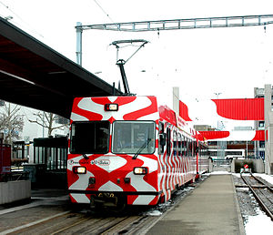
Be 4/4 13 in a new color scheme in Wil
|
|
| Numbering: | 11-15 / 16-17 |
| Number: | 5 + 2 |
| Manufacturer: | FFA BBC / Stadler |
| Year of construction (s): | 1984-85 / 1992 |
| Retirement: | from 2013 |
| Axis formula : | Bo'Bo ' |
| Gauge : | 1000 mm ( meter gauge ) |
| Length over coupling: | 18,400 mm |
| Trunnion Distance: | 12,000 mm |
| Bogie axle base: | 2,300 mm |
| Fixed wheelbase: | 2,300 mm |
| Total wheelbase: | 14,300 mm |
| Payload: | 8.2 t |
| Service mass: | 36.3 t |
| Friction mass: | 36.3 t |
| Wheel set mass : | 9 t (empty) |
| Top speed: | 75 km / h |
| Driving wheel diameter: | 750 mm |
| Power system : | 1200 volts direct current |
| Power transmission: | Pantograph |
| Locomotive brake: | Compressed air, electric |
| Train brake: | Compressed air |
| Coupling type: | + GF + coupling |
| Seats: | 54 |
| Standing room: | 63 |
| Floor height: | 960 mm |
| Classes : | 2nd Class |
| Bt | |
|---|---|
| Numbering: | 111-114 |
| Number: | 4th |
| Year of construction (s): | 1984-1985 |
| Retirement: | 2013-2014 |
| Length over coupling: | 18,400 mm |
| Trunnion Distance: | 12,000 mm |
| Bogie axle base: | 1,800 mm |
| Fixed wheelbase: | 13,800 mm |
| Payload: | 9.0 t |
| Service mass: | 18.8 t |
| Top speed: | 75 km / h |
| Impeller diameter: | 750 mm |
| Wheel diameter: | 960 mm |
| Seats: | 66 |
| Standing room: | 63 |
| Classes : | 2nd Class |
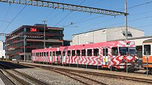
The five electric multiple units of the Frauenfeld-Wil-Bahn delivered in 1984/85 are designated as Be 4/4 11–15 . They were manufactured together with the Bt 111–114 by Flug- und Fahrzeugwerke Altenrhein (FFA). Most of the electrical equipment comes from Brown, Boveri & Cie . In 1992 Stadler Rail AG started operating numbers 16 and 17. With the delivery of the new ABe 4/8 7001–7005 from Stadler Rail , the Be 4/4 11–15 became redundant.
history
With the decision to maintain and modernize the Frauenfeld-Wil-Bahn in 1975, three steps were taken. The first step, which was decided on October 8, 1975, was the introduction of the roll stand. The second step, which was decided on June 12, 1978, was the technical renovation of the route, which included the establishment of a route block and the installation of ticket machines. As a third and final step, the purchase of new rolling stock was inevitable, as the last purchase of new rolling stock was a good 60 years ago. The locomotives taken over from other railways (formerly BD Be 4/4 6–8 (Bj. 1947), FW No. 204–206 and BTI BDe 4/4 5 (Bj. 1944) FW No. 207) no longer corresponded to the increased requirements. The five railcars and four control cars were ordered in 1982. At the same time, a new, modern depot facility was built in Wil, which replaced the old one in Frauenfeld.
Technical
For cost reasons, as many identical parts as possible were used for the railcars and control cars. Both have the same car bodies .
The car body is a welded, self-supporting lightweight steel construction. This is constructed symmetrically, with the floor of the car being at the same height of 960 mm throughout. The automatic doors are designed as two-part swing doors with folding steps and are located above the pivot, they can be unlocked and locked from one side. A semi-automatic + GF + coupling is attached to both ends of the car as a pulling and pushing device . Warm air blowers are installed under the fabric-covered seats in the compartments. Fresh air is supplied from above via a multi-hole ceiling. The fixed compartment windows are equipped with folding skylights. The luggage rack is located lengthways above the window. A glass swing door was installed in the middle to separate the smoking and non-smoking compartments. On the other hand, in contrast to the control car, there was no door to the multi-platform installed in the railcar.
The bogie frame consists of a welded hollow steel beam to which the two motors are firmly screwed. The power is transmitted via two gear stages with a cardan shaft in between. As a result, only the gear stage is not cushioned on the axle shaft. There is also a brake disc for the compressed air brake in the middle of the axle shaft. In addition, there is a cleaning block, a sand device and a wheel flange lubrication device for each wheel. All of this, including the sandboxes, is integrated in the bogie. The power is transmitted via a conventional pivot pin, while the suspension is designed in three stages. The axle suspension and the actual box suspension are designed as steel coil suspension. However, the large steel springs of the secondary suspension do not support the box directly, but rather lead onto a cross-member. This in turn is connected to the car body with two rubber layer elements, which also take over the rotary movement between the bogie and the car body. This also ensures acoustic decoupling. The center distance is 2,300 mm.
All electrical traction equipment, with the exception of the two single-arm pantographs of type ESg 47-2500, the surge arrester and the direct current high-speed switch, are located under the floor of the car. The equipment is divided into two units, each responsible for a bogie. Two mixed-current series motors of type 4 EBO 2052 C from BBC are installed as traction motors in the bogies. These are independent of one another on the load side. The drive motors are controlled by a so-called chopper control . The DC choppers work at a frequency of 440 Hertz. The control for limiting the average motor voltage also allows the drive motors to be fed with 220 or 110 Hertz. Are used reverse conducting thyristor (RCT, English Reverse Conducting Thyristor ), which are connected in series because of the tension for each function takes two thyristors. An electrical recuperation brake with an additional resistance brake is installed, which responds automatically if no feedback is possible. The operation of the electric and pneumatic brakes is separate, but when the electric brake works, the brake cylinder pressure of the pneumatic brake is automatically reduced depending on the braking current in order to prevent overbraking. The vehicle tries to apply the braking force independently with the electric brake. The electrical braking force can be limited for the roll stand operation. A spring-loaded brake is installed as a parking brake. The control takes place via a command transmitter control with which the locomotive driver regulates the pulling force.
Operational
In addition to running the passenger trains, it was also planned that they would run the Rollbock trains in freight traffic. That is why they were given two driver's cabs so that they can be used as a solo multiple unit. However, the two Be 4/4 204 and 206, which had been converted to compressed air brakes and also served as reserve vehicles, usually took over the Rollbock trains.
As a rule, a single railcar coupled with a control car runs as a shuttle train. Multiple traction with a second railcar is also possible. Since their delivery, the five vehicles have been responsible for all scheduled traffic. In 1992, two identical railcars were delivered by Stadler and ABB, these were given the numbers 16 and 17.
With the associated control car, it is possible to convert the rear platform into a lockable luggage and mail compartment . This operation changed somewhat in 2013 with the delivery of the five Stadler ABe 4/8 multiple units, as the 11–15 multiple units were no longer required. Numbers 11–13 and 15 were sold to CJ , number 14 went to ASm together with the Bt 112 control car . The other three driving cars were demolished in 2013 and 2014.
The two newer railcars (numbers 16 and 17) were needed as reserve vehicles. They were revised in 2014 and equipped with the “ZSI 127” train control system. In doing so, they were combined to form an operationally inseparable double unit. After they were no longer needed for the 2019 timetable, number 16 was transferred to ASm in Langenthal as a spare parts donor in August 2019 and number 17 was canceled.
literature
- Kurt Anderegg, Martin Renner and Herbert Weite: The mechanical part of the new commuter trains of the Frauenfeld-Wil-Bahn , in Schweizer Eisenbahn-Revue 2/85 pages 53–56
- Anton Zimmermann and Sébastian Jarne: The electrical equipment of the new Be 4/4 + BT multiple units of the Frauenfeld-Wil-Bahn , in Schweizer Eisenbahn-Revue 2/85, pages 57–60
Individual evidence
- ^ A b Mathias Rellstab, Philipp Wyss: First low-floor multiple unit delivered to the FW . In: Swiss Railway Review . No. 5 . Minirex, 2013, ISSN 1022-7113 , p. 258-259 .
- ↑ a b Rolling stock departures from the FW . In: Swiss Railway Review . No. 11 . Minirex, 2013, ISSN 1022-7113 , p. 556 .
- ^ Hans Waldburger: The Frauenfeld - Wil-Bahn in the technical renovation . In: Swiss Railway Review . No. 5 . Minirex, 1981, pp. 168-170 .
- ↑ Last FW control car disposed of . In: Swiss Railway Review . No. 2 . Minirex, 2015, ISSN 1022-7113 , p. 62 .
- ↑ Annual Report 2014 PDF
- ↑ News in brief . In: Railway amateur . No. 10 . SVEA, 2019, ISSN 0013-2764 , p. 456-457 .


