
Car body

The structure of a railway car , railcar or locomotive is referred to as a car body or locomotive body . Car or locomotive bodies can be built on a frame or be self-supporting on the swivel base of the bogie .
The term car body was originally used for the construction of any multi-track vehicle such as a carriage or horse-drawn carriage .
Construction methods
While in the early years of the railroad the construction of passenger carriages consisted of wood on a solid frame (mostly made of iron), car bodies have been made of metallic materials since the 1920s.
Frame construction

It is the oldest construction. Here, a solid frame (also known as the underframe) is first made, which absorbs all tensile and impact forces, and to which the chassis and also the tensile and impact device are attached. The frame must be correspondingly solid and is usually made of riveted or welded steel girders. In the very early days of the railway, hardwoods and cast iron were also used for the frames of wagons, but neither of them proved themselves. The actual car body is placed on this frame. This can be made much lighter than the stable frame, as the structure only has to hold itself together. However, in the event of accidents, this lightweight construction had regularly led to the wooden car body being separated from the undercarriage and literally smashed. As a result, the car body was also made of steel, which made the car as a whole more stable, but also much heavier.
The frame construction is still common today for freight cars.
Self-supporting construction
Self-supporting construction means the use of a car body that does not have a frame / base; the car body can absorb the tensile and impact forces. As a rule, it is constructed like a square tube into which openings in the form of doors and ribbon windows are made on the sides. The lightweight steel car prototype developed by SWS - which was completed in 1935 - weighed only 25 tonnes (series version 29–30 tonnes), while a similar car with frame and steel box in the conventional design usually weighed around 40 tonnes. This much lighter steel construction also gave rise to the term “light steel wagon”. The self-supporting construction requires good welding technology and was only able to establish itself across the board after the Second World War .
Today self-supporting boxes are the rule, a distinction is made between three different construction methods:
Differential construction
With the differential or raw box construction, a load-bearing steel or aluminum skeleton is first created, onto which non-load-bearing sheets are then attached for planking . Differential design is the simplest and cheapest method of building a car body and was used as standard in vehicle manufacture from 1930 to the late 1980s. Even cars with wooden structure received a new superstructure in the 1950s by differential construction, making the conversion wagon of the German Federal Railways and the Spantenwagen the Austrian Federal Railways emerged. Today the differential construction is used in the field of main railways in the manufacture of car bodies for small series and for special constructions; In the case of trams, on the other hand, it is still widely used in order to be able to guarantee a simpler and more cost-effective repair after a possible collision with road vehicles. The outer panels can dent in an accident and are then replaced. The screws required for this are either covered by strips or arranged outside of the actual field of vision. The differential construction with a steel frame allows thinner-walled car bodies than the integral construction with aluminum, which is particularly important for vehicles with a narrow clearance profile .
Integral construction

In the integral construction, extruded profiles are used which extend over the entire length of the car body and have widths of around half a meter. Before assembling the car bodies for passenger coaches, recesses for the windows are created using a milling machine ; After being welded together, they are expanded to their nominal size again using a milling machine . The underside is also made from extruded profiles so that a self-supporting car body is created. Grooves are created on the underside in order to be able to mount the car body on the bogies and to be able to attach components such as transformers or traction motors in the sub-floor. In the case of locomotives, the car body is open at the top, since the drive components are assembled after the car body has been completed and the locomotive would otherwise not be able to be assembled. The roof structure then consists of lightweight aluminum sheets on which at electric locomotives still pantographs are attached. With the integral design, the rigidity of the car body is achieved through the structure of the extruded profiles, so that no additional load-bearing elements are necessary and a lightweight design is made possible. The integral construction is, as a rule, in connection with aluminum as a material, the construction method used as standard today for the construction of car bodies.
Composite construction
.jpg)
The composite construction is similar to the differential construction: non-load-bearing cladding is attached to a load-bearing frame made of metallic materials; In contrast to the differential construction, however, these are made of non-metallic materials. The hybrid construction can also be assigned to the composite construction; Panels made of aluminum and carbon fiber reinforced plastics are attached to a steel framework . In the course of lightweight construction efforts, this construction method is viewed as promising. For example, with the Next Generation Train, DLR designed a train with a honeycomb-shaped car body structure, which is supplemented at each end of the car with areas that can be deformed under collision effects.
Crash optimization
In the recent past, the designs of car bodies have been continuously optimized with regard to safety aspects in the event of accidents. The starting point for this development was the publication of the 41-page standard EN 15227 with the title “Requirements for the collision safety of rail vehicle bodies” in the middle of 2008. This standard has a number of predecessors. The decisive factor was the SAFETRAIN research project funded by the European Commission and UIC, which ended in 2011. Reference collision accidents were derived from a Europe-wide analysis of collision accidents, which cover the majority of all collision accidents. Computer simulations were then created that determined the optimal arrangement of the energy-absorbing components. The results were then validated with crash tests, which were finally published in 2008 in the standard DIN EN 12663-1 "Strength requirements for car bodies of rail vehicles", which has existed since 2000. SAFETRAIN focused on mainline railways so that other scenarios were considered in further projects such as SAFETRAM until 2004 and SAFEINTERIORS until 2010.
Before this standard came into force, only the energy absorption capacity of impact devices such as buffers and the absorption capacity of longitudinal forces of the car body were defined. When two trains collide, these forces are reached at speeds of 10 to 15 kilometers per hour. The behavior of the car body beyond the dimensioning force was not regulated; only the end walls should be designed to be particularly resistant. In the event of accidents, the car body was often kinked before or after the first bogie; in other cases the car body climbed up and separated from the bogies. In the case of multiple units in particular, this resulted in a risk to passengers. The DIN EN 15227 standard, which today must be met for all new registrations of rail and tram vehicles, defines different scenarios that a train has to withstand without impairing the survival space of the driver and passengers. The scenarios depend on the vehicle type; the following reference accidents apply to mainline vehicles:
- Collision with a stationary identical vehicle at a speed of 36 km / h
- Impact on a stationary freight wagon with a mass of 80 t at a speed of 36 km / h
- Collision with a truck at a level crossing at a speed of 110 km / h (with 15 t in the hit area)
- Collision with a car at a level crossing
Tram vehicles must meet the following parameters according to EN 15227:
- Collision with a stationary identical vehicle at a speed of 15 km / h
- Impact on a solid obstacle with a mass of 3 t at a speed of 25 km / h and an angle of 45 °
Vehicles can be classified in different collision safety design categories CI to C-IV. For example, in category CI an impact at 36 km / h is provided, in category C-III, on the other hand, with a maximum of 25 km / h (in scenarios 1 and 2 for identical vehicles or stationary freight wagons).
Before the standard came into force, the head of a vehicle was seamlessly integrated into the car body structure. In today's rail vehicles, the actual car body structure closes in front of the driver's cab. The driver's cab is now in a safety cage that is deformed in a controlled manner and ensures the driver's survival. With railcars there are now deformation zones and elements for anti-climbing protection on each car body, especially between the individual cars, so that the impact energy can be distributed over the entire train and kinks in the car body are avoided.
- Effects of DIN EN 15227 on the design of multiple units

Stadler Flirt in conventional construction ...
... Stadler Flirt 3 with crash-optimized head module
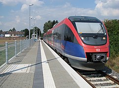
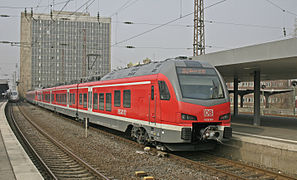
Bombardier Talent in conventional construction ...

... Bombardier Talent 2 with crash-optimized head module
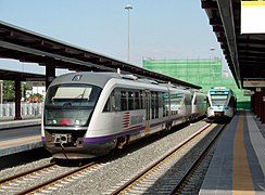
Siemens Desiro Classic in conventional design ...

… Siemens Desiro ML with crash-optimized head module

Alstom Coradia Continental , series 440 in conventional design ...
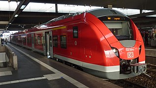
... Alstom Coradia Continental, series 1440 with crash-optimized head module
,_by_Klugschnacker_in_Wikipedia_(4).JPG)


.JPG)

Individual evidence
-
↑ Light steel wagon of the Swiss Federal Railways: built by Switzerland. Wagons and elevator factory Schlieren.
Schweizerische Bauzeitung , Volume 110 (1937), Issue 2 (Part 1) (E-Periodica, PDF; 1.4 MB)
Schweizerische Bauzeitung , Volume 110 (1937), Issue 10 (Part 2) (E-Periodica, PDF; 3.6 MB) - ↑ a b c d e f g Jürgen Janicki, Horst Reinhard, Michael Rüffner: Rail Vehicle Technology . Bahn-Fachverlag, Berlin 2013, ISBN 978-3-943214-07-9 .
- ↑ a b c Iwainsky Heinz: For crashworthiness of trams - the new "Tango" for the TPG for "Crash norm". In: Swiss Railway Review . No. 1/2012. Minirex, ISSN 1022-7113, pp. 136-137.
- ↑ Patrik Kobler: Stadler makes the trains dance: This is where the new Appenzeller Bahn wagons are built. In: Appenzeller Zeitung from April 21, 2018
- ↑ Handout car body in lightweight construction. (PDF) German Aerospace Center , accessed on March 23, 2015.
- ↑ Joachim Winter: New construction methods for the Next Generation Train. ( Memento from March 4, 2016 in the Internet Archive ) (PDF) Institute for Rail Vehicles and Conveyor Technology at RWTH Aachen University , accessed on March 23, 2015.
- ↑ More safety on European rails - New European standard for collision safety of rail vehicle bodies has been published. German Institute for Standardization , August 27, 2008, archived from the original on July 14, 2015 ; accessed on May 1, 2015 .
- ↑ a b Collision safety in rail vehicles . Research information system for mobility and traffic at the TU Berlin. 23rd March 2017.
- ↑ DIN EN 15227 “Requirements for the collision safety of rail vehicle bodies” - recommendations for manufacturers and operators. (PDF) TU Dresden , Faculty of Transport Sciences “Friedrich List”, July 16, 2008; Lecture at the German Machine Technology Society ; accessed on May 1, 2015.
- ↑ Prof. Dr.-Ing. Dr. hc Günter Löffler (professorship for technology of track-guided vehicles): DIN EN 15227 “Requirements for the collision safety of rail vehicle bodies” - recommendations for manufacturers and operators . TU Dresden. July 16, 2008.
- ↑ Galea crash concept. Voith , accessed on May 1, 2015.