Flat plate stirling engine
The flat plate Stirling engine is a design of the Stirling engine with discontinuous control of the regenerator . The force and the stroke are transmitted through a membrane . The motor works even at a low temperature difference.
overview
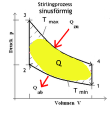
This variant is quite simple in structure and can be produced with a few components. The “displacement piston” is designed as a recuperator , which practically eliminates dead space. Dead spaces (or dead spaces) are all spaces filled with working gas that do not actively participate in the process. The “working piston” is a gas-tight membrane or bellows. The flat plate system has a large transfer area for heating and cooling in relation to its volume. The front wall is heated (e.g. solar radiation, hot water or hot gas) and the rear wall is cooled. Due to the discontinuous control of the displacer, the sinusoidal movement originating from the crankshaft is divided into two jerky movements of the regenerator. As a result, the cycle is better extended in the corners. The two pV diagrams (pressure-volume diagrams) show this fact. The yellow marked areas represent the useful work of the process. How to use the formula
the temperature difference and volume ratio must be made as large as possible. If the regenerator is replaced by a simple displacer, this simplification reduces the temperature difference and thus the useful work. Possible energy sources for low-temperature applications are direct solar radiation, hot water from flat-plate collectors , geothermally heated water and industrial waste heat.
functionality
The flat-plate Stirling engine according to Ivo Kolin essentially consists of the following components:
- flywheel
- Labor Chamber
- Displacer / regenerator
- Warm plate (heating side)
- Cold plate (cooling side)
- Working lever
- Push rod to crankshaft
- Push rod joint
- Working crank
- Displacement crank
- Bracket for displacement pushrod
- Adjustable stops
- Drive lever for displacer
- Displacement pushrod
- Damping springs
- Rotary joint for cold plate
- Swivel joint working lever
- crankshaft
In the gas-tight closed working chamber only one plate moves, the so-called displacer (3), which is coupled to a flywheel (1) by means of a drive lever (13) with which mechanical work can be carried out. The displacer also has a regenerator function ( heat storage ).
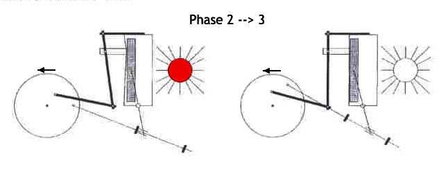
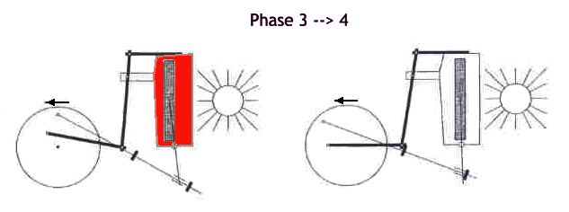
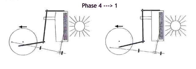
The engine's work cycle can be divided into 4 processes (phases 1 to 4). The following description refers to the sequence of images given below.
Phase 1 ⇒ 2
The working gas (air, hydrogen, helium etc.) in the working area is compressed when the worktop (membrane, cold side) is pressed in. The displacer / regenerator remains close to the hot plate side.
Phase 2 ⇒ 3
If the gas volume is small, the displacer / regenerator flips over from the hot side to the cold side. The working gas flows through the porous displacer / regenerator from the cold side to the warm side and absorbs the stored heat.
Phase 3 ⇒ 4
The heated gas expands and pushes the worktop / membrane outwards. This lifting movement is transmitted to the flywheel and is the work cycle .
Phase 4 ⇒ 1
With a large gas volume, the displacer flips over from the cold to the warm side. The working gas flows through the porous displacer / regenerator and transfers heat to it (pressure reduction).
Theoretical explanation
The working medium is periodically expanded and compressed in a cycle of two isotherms and two isochores . In the pv diagram , the area enclosed by the graph (yellow) is the work done by the machine.
Cycle 1 is an isothermal expansion where work is done by the gas and cycle 2 is an isochoric cooling. Cycle 3 is isothermal compression and cycle 4 is isochoric heating.
The principle of this machine is based on the so-called Stirling cycle . The machine operates between the high temperature T max and the low temperature T min . The difference between these two temperatures is decisive for the degree of efficiency , which describes the efficiency of the machine.
advantages
Compared to piston-operated Stirling engines , the diaphragm seal offers a much simpler sealing of the gas space (no piston rings, less friction losses). In addition, thanks to thinner displacers, flat housings enable more working gas to be used and the heat exchange surface to be increased. This “low-tech” engine can be recreated yourself with little effort, in contrast to other Stirling engines.
history
Since 1970, Professor Ivo Kolin (born September 23, 1924 in Zagreb, † 2007, professorship at the University of Zagreb ) has built 16 test engines. In 1983, with engine no. 16, it reached an operating range with a temperature difference of 16 Kelvin for the first time. In 1989 Kolin gave a lecture on his developments at the 19th Intersociety Energy Conversion Engineering Conference (IECEC) in San Francisco . Senft developed a model that works with a temperature difference of 0.5 Kelvin.
literature
- Ivo Kolin: Stirling motor: history, theory, practice . contributions to the 5th International Stirling Engine Conference. Inter University Center, 1991.
- Walter Kufner: Stirling engines of simple design. Hergensweiler 1995.
- Brad Ross (Ed.): Stirling Machine World. UNITED STATES.
- F. Schmelz: The performance formula of the Stirling engine. 2nd Edition. Polygon-Verlag, Buxheim 1994, ISBN 3-928671-07-3 .
- F. Steimle: Stirling machine technology. CF Müller Verlag, ISBN 3-7880-7583-X .
- M. Werdich, K. Kübler: Stirling machines. Basics - technology - application. 9th edition. Ökobuch-Verlag, 2003, ISBN 3-922964-96-6 .
- Dieter Viebach: The Stirling engine simply explained and easily built. 9th edition. Ökobuch-Verlag, 2010, ISBN 978-3-936896-54-1 .
Web links
- Ivo Kolin, Sonja Koscak-Kolin, Miroslav Golub: Geothermal Electricity Production by Means of the Low Temperature Difference Stirling Engine . (PDF)
Individual evidence
- ^ Ivo Kolin: Stirling motor: history, theory, practice . contributions to the 5th International Stirling Engine Conference. Inter University Center, 1991.
- ↑ ivokolin.com ( Memento of the original from November 11, 2014 in the Internet Archive ) Info: The archive link was inserted automatically and has not yet been checked. Please check the original and archive link according to the instructions and then remove this notice.


